They adorn the ends of Cat5 network patch cables and the flat satin cables that come with all-in-one printers that we generally either toss in the scrap bin or throw away altogether. The blocky rectangular plugs, molded of clear plastic and holding gold-plated contacts, are known broadly as modular connectors. They and their socket counterparts have become ubiquitous components of the connected world over the last half-century or so, and unsurprisingly they had their start where so many other innovations began: from the need to manage the growth of the telephone network and reduce costs. Here’s how the modular connector got that way.
Service as a Service
For the first 80 years or so of the US telephone network, the Bell Company called all the shots. They owned absolutely every bit of equipment in the system – the wires on the poles, the switchgear in the central offices, microwave links, and even the phone sets in customer homes. They had complete control over every aspect of the delivery of their services, and used their monopoly to build an incredibly integrated and durable system.
But with great power comes great responsibility, or in the case of a complex technological system prone to breakdown no matter how robust it is, a great support burden. Customers were completely reliant on phone company technicians for everything. Want a phone moved to another room? That’s a service call. Dog chewed the cord between the set and the wall? Service call. Junior got the scissors and decided to clip the handset cord? Most definitely a service call. Some services were charged back to the customer, but even for phones built like a battleship with a design life of 40 years, wear and tear eventually add up.

Sinking ever more money into customer service calls, AT&T decided to look into ways to minimize costs in this area. With mountains of service tickets to provide raw data, they discovered that by far the most common calls were for broken cords between the base and the handset. That’s understandable; the handset cord is twisted and kinked, and despite ample strain reliefs at stress points, eventually the cord frays and breaks. Not only were there a lot of broken cord calls, but each one required a good chunk of the technician’s time to correct, as the phone had to be disassembled for the dodgy cord to be replaced.
To reduce the service burden, in the late 1960s AT&T turned the engineers at Western Electric, its manufacturing arm, on the problem. The team, including Edwin Hardesty and Charles Krumreich, looked at the specs. They knew they needed four conductors, and that the connector had to be easily and rapidly disconnected in the field. The connector would have to have strain relief built in, be easily manufactured, and be cheap. It was also desirable to have the handset connector be generally useful, in particular for replacing the cord between the phone and the wall, another frequent cause for service calls.
An Easy Squeeze
It’s not exactly clear where the inspiration for a rectangular molded plastic connector came from, except that Krumreich had patented a similar connector in the mid-1960s. The earlier design had a lot of familiar elements: multiple parallel conductors, plastic channels to isolate and insulate each circuit, insulation displacement contacts in the plug, and springy wire contacts in the socket. The later design changed a few things, notably replacing the spring wire contacts in the socket with fixed blades, but on the whole the designs were very similar.
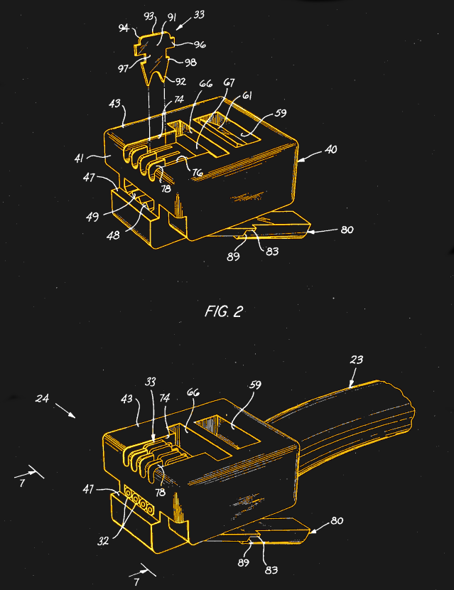
The big difference was in the thought given to how the connectors would be used in the field, and how they would be manufactured. Focusing on insulation displacement meant that field technicians would be able to mass terminate the connector with a simple crimp tool, and made the connector easier to manufacture in the huge numbers that would be needed for a system-wide conversion. Molding the plug body also meant that strain relief would be integrated into the plug, in the form of a flexible bar that would be crimped down onto the cord jacket after the electrical connections were made.
The design would soon be refined, returning to spring wire contacts in the socket and replacing the original metal latch that locked the plug into the socket with a molded plastic latch. But the basic design of the modular plug was set. New phone designs like the Trimline phone, where the handset contained the dial or keypad, would be among the first phones to use the new cords, and during the 1970s phone companies across the country retrofitted millions of existing phones.
As the 1980s rolled around and the AT&T monopoly began to break up, the new modular connectors would play an important role in democratizing the phone system. For the first time, customers could go to a retail store and buy whatever phone they wanted outright, rather than leasing one of the “any color as long as it’s black” phones. The modular connector made customer self-connections possible for the first time; unfortunately, it also made cheesy corporate how-to videos inevitable.
Registered Jack of All Trades
The powerful combination of good design, easy extensibility to more or fewer conductors, and the saturation of the market thanks to a large installed base all led to the general acceptance of the modular connector across a wide range of industries. This was helped by the 1976 mandate by the Federal Communications Commission that phone system connections be standardized for interoperability, primarily to allow customers to connect their own equipment to the telephone network.
The mandate termed these specifications registration interfaces, and the modular connectors became known as registered jacks, or RJ for short. Six-conductor RJ11 became the standard for connecting phones to the network, while RJ14 with four conductors was specified for handset to base connections. With roots in the telephone system, the eight-conductor modular connector eventually became the standard for Ethernet connections under a separate set of standards; it’s commonly but incorrectly referred to as RJ45, which is similar but has a keying lug built into the socket and plug.
Modular connectors have stood the test of time for nearly 50 years now, and while the design isn’t perfect — looking at you, little plastic latch who snaps off — its has proven to be remarkably adaptable to a wide range of applications. That it started with a need to make field service easier seems fitting in a way.
[Featured images: University of Vale do Taquari]


*first! yeah for me* Attaching plugs isn’t really a technical problem, it is more to do with the use of the device. working in the IT field i noticed these plugs were very good at maintaining a connection. However, my buddy comes over to play on my network once a week and manages to destroy the latch on the plug within 3-4 months…I bought a Monoprice flat cable and it is quite durable…choose your cable/friends/users wisely
We used this type of cables. Work pretty good.
https://www.elive.co.nz/images/PLE-C5E-PP.jpg
That “little plastic latch who snaps off”,
often does so when dragging through a bunch of other wires under the desk.
The plastic latch was a big mistake. Should have been a small indentation instead, mating with a metal clip in the socket.
You are hired! Soooo right.
Better to have the part that wears out on the cable than in the socket.
The latch in the socket would be metal, the connector would have a plastic indentation. The connector would still wear out first, it just wouldn’t have a flimsy hook-like protrusion that snags other cables and breaks.
Till Bob in accounting trips over the cable and pulls the whole wall plate out of the wall. Though that happens now..
I wondered what happened to Bob after he left here. He also likes to plug cables into anything that looks like it will fit so watch him!
fuck no! better have plastic latch breaking off (or use protected ones, this is a solvable problem, after all), than having sharp metal thingies protruding from rackmount devices, ready to tear you to shreads.. (and then break/bend).
The ends are easy enough to replace; I’ve made up literally thousands in a week long contract once. Those were 10G cables, too. I could do it in my sleep. Just get a tool, some RJ-45’s, and get cracking!
The other problem with the plastic latch is that, during crimping, they can get pressed down hard enough that they don’t spring back up again, and thus don’t keep the cable in the socket.
Throw away your crimping tool and buy a decent one.
And / Or buy decent connectors. The cheapest chinese stuff is sometimes so far out of tolerance that the latch won’t hold at all.
Might explain the tab of plastic over it that the better cables have, but it’s still a weak point.
Ahh, the “anti-snag” cable. Maybe someday they’ll use a plastic that doesn’t become hard as granite after a couple years.
I find I have to cut that off just to release the cable
All the damn time.
Not to mention they don’t fit in the back of more than few Dell servers. Others too I’m sure.
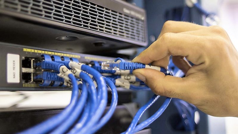
thus the need for those little arcs like the ones in the feature picture. The problem with those though is either they are too stiff to depress or people mess up their placement and put them under the latch… The dude in the picture is holding one that’s messed up too!
You can buy sheathed patch cords or even buy the sheath separately if you need to crimp your own connector…
Then you can happily drag the cable “backwards” through hell and back and the latch will still be fine.
I just put a little bit of electrical tape around the connector to hold down the latch before pulling the wire out of what ever mess of cables there is. Never broke off any of these tabs…
We throw out loads of cables because one or both latches broke off. It’s cheaper just to bin it than to come back for the unreliable connection. Exceptions are cables built into walls or other objects, but that’s just trading a big hassle for a smaller hassle.
Buy a crimper and bag of connectors and save yourself a packet. Mind you, when you’re starting out it’s good to have a cable tester on hand too.
I still use a cable tester, but that’s just because it’s good to be sure to start than to have to backtrack later.
There are versions with a latch that’s harder to break.
Either that, or a flexible “boot” that covers the latch whilst still enabling it to be pressed down.
There’s also M12 for industrial.
https://www.connectorsupplier.com/m12-versus-rj45-ethernet-connections-on-the-factory-floor/
Is M12 the one used in sensor interfaces? (like a capacitive sensor to a controller)?
It’s one of them, I know there are also M5 and M8
I have a military Geiger counter, the DPS-68M1, from a tank/armored vehicle that used M12 style connectors for power and sensors. There are some pictures of interior on elektroda.pl forum:
https://www.elektroda.pl/rtvforum/topic2727644.html
I’m currently really liking the 10 pin XLR from Neutrik, 8 pins rated for Cat5e and 2 heavy pins for power.
Also, Ethercons, Ethercons everywhere.
So if it’s incorrect to call what is commonly known as an RJ45 an RJ45, what is it?
According to Wikipedia, it is 8P8C
Yes, that was the question that went through my head as well.
We need answers!
RadioShack,
“You’ve got questions, we’ve got answers!”
B^)
“You’ve got questions? We’ve got dumb looks!”
The designation RJ11 (“registered jack”, IIRC) is the telephone network side (sized for 6 conductors, but generally only 4 used in POTS– 6P4C, six position, four contact, often with only 2 conductors– but sometimes 6P6C for multiline phones). Modular was the popular name. RJ45 is the P8C used for four twisted pair network cables.
The RJ designations, overall, refer to the FCC registration for a particular application, and, strangely enough, do not specify the details of size or geometry. Only the contacts and uses thereof.
Registered Jack type 45 (RJ45) was originally (and technically still is) a connector that looks like what is commonly called a RJ45 (8P8C) connector but it has a physical key on the plug and a key-way in the socket. You will often see something like this used for power connections on Plain Old Telephone Service (POTS) equipment like Telephone Answering Devices (TAD) or wireless phone base stations. Sometimes it is still used for RS-485 current loop connections and on Point of Sale (POS) equipment as well.
The connector used for Ethernet connections is a 8 Position 8 Conductor (8P8C) Insulation Displacement Connector (IDC) and I don’t think there is any official standard for the connector or socket. There is however two standards named T568A and T568B that define the pair (color) to position of the wires for the 8P8C connector.
All of this is rather semantic now because if you ask for a RJ45 plug or socket you will get a 8P8C plug or socket because that’s what you really wanted anyway.
For more on why the T568A/B standards are the way they are, with the weird split pair in the 3/6 positions, check this comment I wrote recently: https://www.reddit.com/r/AskElectronics/comments/8lpfnf/why_are_rj45s_crimped_the_way_they_are/dzi6svo/?context=0
HEY YOU GUYS (at Hackaday)
I continually see excellent posts like this and dutifully add a bookmark only to find some of those bookmarks invalid after some website does an update to make their web page “cooler”.
Is there some place besides creating a HAD.io project that you could store these? Something like GitHub that could be cloned locally?
Hell, I’d help edit it if you didn’t want to spend the time more than to just add a link to your site. (BTW, if you change your web page structure I will lose a ton of info)
And what else ? an “edit” button while you´re at it ???
Well…now that you mention it?
Do “other” WordPress entities allow comment editing?
I don’t really understand what you’re complaining about. Reddit permalinks will almost certainly continue to work as long as Reddit is online, unless the poster deletes their post or comment, which is rare IME. I haven’t experienced Hackaday ones breaking either, but if they did, I think the link would still get you to the right post, and you could look through the comments for the right one.
For other websites, which do indeed go down sometimes, why not use the Wayback Machine? It even has text search now!
Nice explanation in the link. I finally understand! In the original 8 pin standard, Pins 4-5 are tip and ring for Line 1, pins 3-6 Line 2, pins 1-2, 7-8 are for data. But why wasn’t the default data path for 10BaseT Ethernet pins 1-2 and 7-8? Instead, pins 1, 2, 3, 6 are used for the 2 pair data path… using one data pair and one voice pair for Ethernet.
https://www.arcelect.com/10baset.htm illustrates this. Only the TP-PMD standard used the designated data pairs.
That’s a very good question, and I don’t have a good answer! My intuition says it probably had to do with avoiding some other thing that was on 7-8 at the time, and is long since forgotten now.
I would think that somebody has thought of using the last 2 pins for power in case external power is needed.
Back than standardized PoE wasn’t a thing yet.
Found it: https://en.wikipedia.org/wiki/StarLAN
Predecessor to 10base-T.
Okay, here we go: https://en.wikipedia.org/wiki/StarLAN was a predecessor to 10base-T.
They were doing it in 1983, and T568a didn’t come out until 1991. So the connector and pinout might not have even been particularly standard at the time, and the page there describes the wiring in terms of pair colors, rather than pin numbers. Which is a sensible way for telephone people to think of things.
The first pair (blue) was used by voice, so they just used the next two (orange and green) for data. Brown was the “last pair” and its preferential position in the jack might not have been solidified yet. If anything, you might’ve expected the last pair to get the worst (3-6) spot, with the ones used by data having gotten the good data (1-2, 7-8) spots. But that’s not what TR-42 ultimately decided in 1991. So the orange pair (telephone “line 2”) got the 3-6 pins to maintain compatibility with analog phones, part of the compromise mentioned above. It’s not a bad split and apparently worked fine for 10base-T anyway.
Holy crap… their DIY replacement jack was brilliant. ~4:45 in the video. Little clips that popped onto the existing screws. No stripping wires, that was a great idea to let anybody do the conversion.
Anyone remember the MMJ connections used on DEC kit, where the clip was offset? Pain in the backside..
I still run into those occasionally. Usually in that old maintenance dude’s pile of crap he hasn’t thrown out since he returned from ‘Nam.
Yup. Years ago my company had a booth at a trade show and there were several VAXstation kiosks. There were spaces intended to hide the CPU’s with just the keyboards/mice/monitors showing but someone forgot to measure the lengths of the cables and the keyboard cables wouldn’t reach. It’s 7PM the night before and I thought about going to Radio Shack to get extension cables, but the darn MMJ connectors nixed that. We had to improvise and prop the CPU’s on boxes high enough to connect the keyboards and hide them with black cloth.
They showed up again on the LEGO Mindstorms wiring, with the clip offset to the other side. I think some MMJ crimpers could have a part flipped around to accommodate.
And here is how to make such a plug: http://philohome.com/nxtplug/nxtplug.htm
Yes. Put in one of the last VAX 11/780’s they sold at a shipyard. Got to know MMJ and eithernet vampire taps.
Great post!
Never bothered to read the wiki article regarding RJ (is suppose there is one ?!).
Probably a large number of wikis contain articles on that topic.
Why do the size numbers have nothing to do with the number of contact positions? With D-subminiature they do.
They do. The “p” is the number of positions, the “c” is the number of contacts loaded.
4p2c is basically never seen.
4p4c is a handset cord.
6p2c is a one-line plug.
6p4c is a two-line plug, and most of the 6p’s in the wild have 4c’s loaded.
6p6c is pretty rare, shows up on commercial PoS electronics among other things.
8p8c is the only 8p variant made in any volume, and being discussed here.
10p10c shows up on UPSs, PoS equipment, certain RS232 terminal servers (Cyclades, Digi), etc.
All the 4p plugs are tiny, 6p plugs are medium, 8p plugs are larger, and 10p plugs are weirdly huge.
6p6c is used by a couple of audio vendors for AC power…Which, in retrospect, was a Very Bad choice.
4p2c is used in dsl modems and telefone lines in a lot of countries.
Canada here. I see only 4P2C for landline phones now—I don’t know how long it’s been this way. That’s what MFPs have for the fax port, at least, and they come with 2-conductor flat cables with 4P2C plugs on them. I think my old MacBook has a 4P2C modem port. (Neither of my current laptops has a modem.) I haven’t unplugged my landline phones in a while, but I think they have the same.
I was once on an IEEE standards committee and became “lunch friends” with a fellow from Bell Labs. Talking one day, I mentioned what a brilliant piece of work that connector (family) was, except for one thing — every time you tripped over the cord it either ripped the wires out of the plug or the plate out of the wall. I asked why they hadn’t slightly altered the shape of the latch so it would disconnect without damage?
He said that was a good question, that he knew someone at the labs who wold know the answer, and that he’d call that evening.
Next day, he told me that the connector was not intended to be “unpluggable” at all, but it was just an easy way to make semi-permanent connections in the field. He said the original jack was recessed so that it took a tool to release the latch.
Interestingly, the AT&T-installed wall jack for the DSL cable to my AT&T modem is recessed and takes a tool, but the jack on the modem (other end of the same cable) is not.
I have came across those jacks int he UK .. had to use a small jewlers screwdriver to release the catch.
Had to spec something similar to allow for a non-easily removable and low profile (depth) ethernet cable connection on some kit to “secure it”.
Was an off the shelf part thanks to this modular design.
Why the flipping heck though, can a male USB-A fit into an RJ47/8P8C socket?
Reaching around the back of a computer without looking, trying to feel the usb socket ,and then being able to shove a usb into the ethernet socket — this should not ever happen. Bad design right there.
Ask the USB-IF!
Some of the crazy combo USB+SATA plugs are pretty cool, or at least were, back when USB2 was a big hindrance on external disks. These days USB3 makes ’em a lot less relevant.
But why all that stuff is the same size as 8p8c, I have no idea!
Because it’s usually harmless to do that? The Ethernet connector should have no voltage from any of the pins to anything outside the port, because they’re galvanically isolated (unless it’s a PoE source, but that should have overcurrent protection), and the pins will spring back up when you take the USB plug out. You’ll either feel it’s not quite right while plugging it in, or notice that your USB device hasn’t been recognized, and investigate where you plugged it in.
So in the US you also have a RJ-jack in the wall to connect your phone to? thats ingenious. In Sweden we have a special huge Sweden-only jack. The only advantage is that you can stack multiple pass-through connectors on top, connecting multiple devices to the same jack.
https://en.wikipedia.org/wiki/Swedish_telephone_plugs_%26_sockets