There was a time when any hi-fi worth its salt had a little row of sliders on its front panel, a graphic equalizer. On a hi-fi these arrays of variable gain notch filters were little more than a fancy version of a tone control, but in professional audio and PA systems they are used with many more bands to precisely equalise a venue and remove any unwanted resonances.
On modern hi-fi the task is performed in software, but [Grant Giesbrecht] wanted an analogue equalizer more in the scheme of those fancy tone controls than the professional devices. His project makes for a fascinating foray into analogue filter design, as well as an understanding of how an equalizer combines multiple filters. Unexpectedly their outputs are not mixed because it proves surprisingly difficult to ensure all the filters have the same gain, instead they are in series with the signal path passing through all filters.
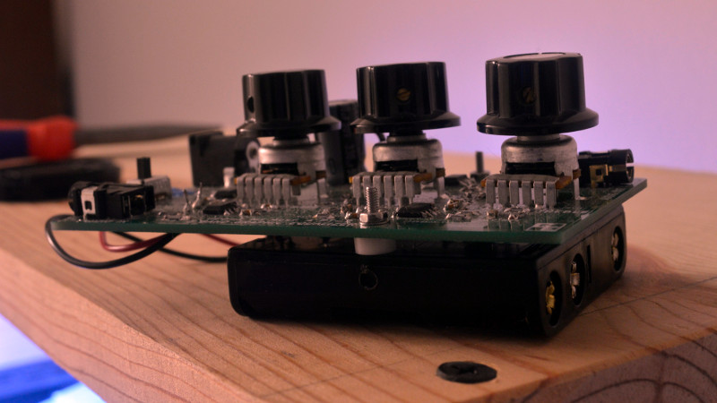
The resulting equalizer is neatly built upon a PCB with a 4-AA-cell power supply, and makes for a self-contained audio component. Unexpectedly such analogue equalizer have been few and far between here at Hackaday so it’s particularly pleasing to see. We’re more used to graphical displays for off-the-shelf devices.


“Worth its salt”? Shouldn’t that term be reserved for humans? Because the idiom refers to _being paid_ for being competent at one’s job.
Anyway, analog EQ seems like the logical choice when your source isn’t even digital, eg a live performance. One only needs to repeat the bandpass circuit for every band. I remember plots where the first and last band were also bandpass which come to think of it should’ve been low- and high-pass.
Presumably for an object the implication of “worth its salt” is “worth the purchase price”.
its interesting to read of his issues with the need to put the stages in series rather than sum their outputs.
equilizers Ive played with in the past have definently had the filters in parallel rather than series. I noticed he is adjusting the gain of the stage rather than attenuating the output of each filter which is more along the lines of what I have seen in the past.
In parallel? Interesting. So what happens when a particular input frequency is on the high side of a lower frequency filter (and shifted -90 degrees in phase), and at the same time on the low side of a higher frequency filter (and shifted +90 degrees in phase). What happens when that signal gets summed at the output of those two filters?
Assuming the component values are chosen wisely, it turns out not to be a problem. The bandwidth of each cut/boost circuit is narrow enough that the phase shift midway between adjacent frequencies is much lower than +/- 90 degrees. I’m pulling numbers out of thin air here, but think of values between +/- 20 degrees and +/- 60 degrees.
SPICE works well in simulating such circuits and the results are educational.
Here’s a lesson on equalizers with some sample schematics:
http://www.geofex.com/article_folders/eqs/paramet.htm
I remember these 3-band equalizers being available as kits when I was a kid. Made me learn about op-amps.
“… to precisely equalise a venue and remove any unwanted resonances,” a real pro would use a parametric equalizer instead. It allows you to precisely notch out a resonance with a precise centre frequency and bandwidth, unlike the blunt instrument the graphic equalizer is.
It’s interesting to look at the design of parametric equalizers and how demanding they are of opamps when you try to push them to narrow notches. Say… sounds like an excellent HaD tutorial…
When you called it an analogue ‘graphic’ equaliser, I was really hoping for a little CRT that showed you a simulation of your filter… Indeed I suspect this doesn’t qualify as a graphic equaliser unless it actually has some form of graphics.
The relative position of the sliders – a graphic EQ should feature sliders – can be seen as a curve. Not very high-res in a 3 band EQ but a 11 or 13 band equalizer does the trick quite nicely. The higher end pro EQ’s often put a LED on the sliders so you can also see the curve in the dark of a concert hall
Most people’s experience with audio equalizers ends with the multi-band “graphic” equalizer where the visible curve of the faders approximates the response. In fact, there’s considerable overlap between the bands, such that if one control is at max boost, and the adjacent control at max cut, the net effect is a much smaller boost/cut over that point.
Now, if you need a SERIOUS audio frequency tool for solving a tough problem like a bad room resonance or a problem frequency, you want a parametric eq, Here’s a useful circuit from the peak of the analogue age:
https://www.paia.com/manuals/docs/6760_Parametric_Equalizer_200.pdf
From a learning perspective, it’s interesting to use separate amps for each stage, but in a practical design all the different filters can be summed together into the feedback path of one op-amp.
https://cdn.eeweb.com/articles/articles/3-band-graphic-equalizer-circuit-1326384498.gif
This also solves the gain issue, since they’re all going through the same gain stage.
Looks like you’re re-inventing the wheel. Not necessarily a bad thing. Some reference materiel:
Texas Instruments, “An Audio Circuit Collection” parts 1, 2, and 3
National Semiconductor, “1976 Audio ?Handbook”, section 2.14
http://www.guitarscience.net/tsc/marshall.htm
Back in my audio days, Audiosource equalizers were awesome. Especially the ones with built in pink and white noise sources for room acoustic tuning. They came with Led displays and a little microphone. I seem to remember the high ones had motorized sliders and autotuned themselves for a flat response in the installed room.