Laser aficionado [Martin Raynsford] has built up experience with various laser cutters over the years and felt he should write up a blog post detailing his first-hand findings with an often overlooked aspect of the machines: aiming them. Cheap diode laser cutters and engravers operate in the visible part of the spectrum, but when you get into more powerful carbon dioxide lasers such as the one used in the popular K40 machines, the infrared beam is invisible to the naked eye. A secondary low-power laser helps to visualize the main laser’s alignment without actually cutting the target. There are a couple of ways to install an aiming system like this, but which way works better?
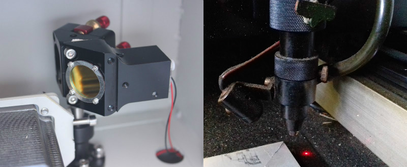
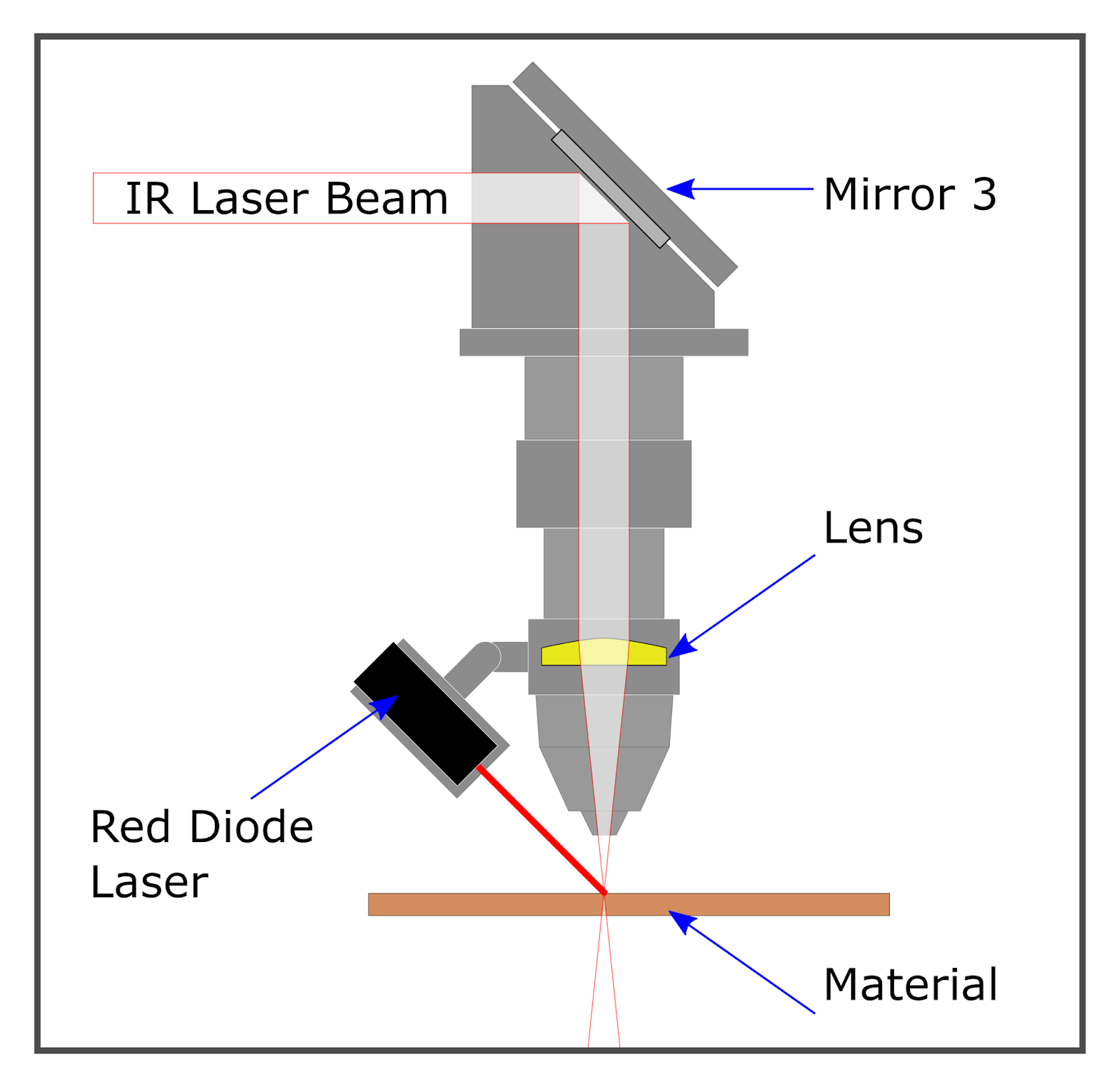 [Martin] explains that there are basically two schools of thought: a head-mounted laser, or a beam combiner. In both cases, a small red diode laser (the kind used in laser pointers) is used to indicate where the primary laser will hit. This allows the user to see exactly what the laser cutter will do when activated, critically important if you’re doing something like engraving a device and only have one chance to get it right. Running a “simulation” with the red laser removes any doubt before firing up the primary laser.
That’s the idea, anyway. In his experience, both methods have their issues. Head-mounted lasers are easier to install and maintain, but their accuracy changes with movement of the machine’s Z-axis: as the head goes up and down, the red laser dot moves horizontally and quickly comes out of alignment. Using the beam combiner method should, in theory, be more accurate, but [Martin] notes he’s had quite a bit of trouble getting both the red and IR lasers to follow the same course through the machine’s mirrors. Not only is it tricky to adjust, but it’s also much more complex to implement and may even rob the laser of power due to the additional optics involved.
In the end, [Martin] doesn’t think there is really a clear winner. Neither method gives 100% accurate results, and both are finicky, though in different scenarios. He suggests you just use whatever method your laser cutter comes with from the factory, as trying to change it probably isn’t worth the effort. But if your machine doesn’t have anything currently, the head-mounted laser is certainly the easier one to retrofit.
In the past, we’ve covered a third and slightly unconventional way of aiming the K40, as well as a general primer for anyone looking to pick up eBay’s favorite laser cutter.


The solution is to use two line generators instead. This model also includes air assist and a third mount for height setting
https://www.thingiverse.com/thing:1270827
2-3 head mounted lasers is also a good option. It’s not like they’re expensive. This has the advantage of indicating position and focus (if all the lasers are hitting in the same spot, its at the focal point).
The KISS approach. It worked for the Dam Busters!
Predator style. This I like.
Better yet, get yourself a cheap laser line level. Extract the laser. Mount three of them and they’ll always cross in the middle no matter the head height.
Yeah, that’s what I did: https://hackaday.io/project/25749-targeting-laser-for-laser-cutter
2 lasers, and use a camera/motors to automatically line them up?
“there is an extra lens to clean” – not really. The beam combiner, along with the first mirror, never gets dirty unless the machine is constructed completely wrong.
I prefer a pivoted mirror that flips into the beam path for setup and out of the path at other times, scorch made a simple device from an led torch which seems to work well.
Cross hair pattern worked fine for me. Line it up on one of the axes and then the other axis might be a little off.
On our system the red laser is on a carriage which moves into the primary beam path. The added benefit of this is that the limit switch on the carriage and the enable signal disable the main laser when it leaves the stop (via 2 fully independent paths). Red dot = machine safe (relatively speaking ;-)
I prefer the beam combiner. If you do one yourself you need to give the laser diode vertical and horizontal translation and then the beam combiner on a kinematic mount. Use translation to bounce off the beam combiner where the CO2 beam passes through and then use a piece of thermal paper 10-20 feet away to line up the diode dot and the CO2 beam position.
You will lose a bit of power with a beam splitter, a watt or two depending on the power of the laser. But you lose power off each mirror bounce and the lens anyway.
I’ve experimented with drilling through the magnet of a large loud speaker, making a hole in the center cone and mounting a lens to it.
It works really well for high speed high accuracy focusing.
I’ve been tempted to make it 3D or make a version that also has piezo discs for fine adjustments on top of the speaker cone movement but as I didn’t need it I never got around to it. The drilling was slow and a little fiddly.
I use 2 line lasers, each mounted 9, degrees apart pointing at the surface to be cut. Because each line in crosses the cut point, and are 90 degrees apart, you always have a crosshair exactly at the cut point. Irrespective of the Z height.
Is a combiner necessary? Wouldn’t a flipping mirror like in SLRs be enough? Is there any reason to have both lasers running at the very same time?
The flipping mirror is what you’d see on high end lasers. The mirror works as a shutter, deflecting the main laser beam into a liquid-cooled absorber as well as sending a red aiming beam down the path when closed.
The other other way to go is to add LED’s around the beam as it enters the main chamber. There are a few examples of this around the place now and since the video i replaced white for RED leds and it works much better. at least with this method you know there are no alignment issues…ever.
https://youtu.be/N-IoCycQCk4