An Englishman’s Home Is His (Drone-Defended) Castle

Retiring to the garden for a few reflective puffs on the meerschaum and a quick shufti through the Racing Post, and the peace of the afternoon is shattered by the buzz of a drone in the old airspace,what! What’s a chap to do, let loose with both barrels of the finest birdshot from the trusty twelve-bore? Or build a missile battery cunningly concealed in a dovecote? The latter is what [secretbatcave] did to protect his little slice of England, and while we’re not sure of its efficacy we’re still pretty taken with it. After all, who wouldn’t want a useless garden accoutrement that conceals a fearsome 21st century defence system?

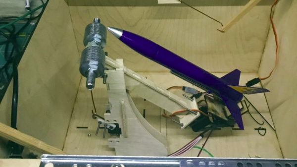
The basic shell of the dovecote is made from laser cut ply, in the shape of an innocuous miniature house. The roof is in two sliding sections which glide apart upon servo-controlled drawer runners, and concealed within is the rocket launcher itself on a counterweighted arm to lift it through the opening. The (toy) rocket itelf is aimed with a camera pan/tilt mechanism,and the whole is under the control of a Raspberry Pi

It’s understood that this is a rather tongue-in-cheek project, and the chances of any multirotors falling out of the sky are somewhat remote. But it does serve also to bring a bit of light back onto a theme Hackaday have touched upon in previous years, that of the sometimes uneasy relationship between drone and public.

Raspberry Pi PoE Redux

[Martin Rowan] was lucky enough to get his hands on the revised Power Over Ethernet (PoE) hat for the Raspberry Pi. Lucky for us, he wrote it up for our benefit, including inspection of the new hat, it’s circuit, and electrical testing to compare to the original hardware.

You may remember the original release of the PoE hat for the Raspberry Pi, as well as the subsequent recall due to over-current issues. In testing the revised board, [Martin] powered a test load off the USB ports, and pulled over an amp — The first iteration of the PoE hat would often trip the over-current protection at 300 milliamps.

This afternoon, the redesigned PoE board was officially released, and the post mortem of the problem documented in a blog post. It’s a lesson in the hidden complexity of hardware design, as well as a cautionary tale about the importance of thorough testing, even when the product is late and the pressure is on.

The PoE hat converts 48 volt power down to a 5 volt supply for the Pi using a flyback transformer. The problem was that this transformer setup doesn’t deliver clean steady 5 volt power, but instead provides power as a series of spikes. While these spikes were theoretically in spec for powering the Pi and usb devices, some Raspberry Pis were detecting those spikes as too much current pushed through the USB ports. The official solution essentially consists of better power filtering between the hat and the Pi, flattening that power draw.

We’re looking forward to getting our hands on this new and improved PoE Hat, and using it in many project to come.

Using E-Paper Displays For An Electronic Etch A Sketch

Electronic things are often most successful when they duplicate some non-electronic thing. Most screens, then, are poor replacements for paper. Except, of course, for E-paper. These displays have high contrast even in sunlight and they hold their image even with no power. When [smbakeryt] was looking at his daughter’s Etch-a-Sketch, he decided duplicating its operation would be a great way to learn about these paper-like displays.

You can see a video of his results and his findings below. He bought several displays and shows them all, including some three-color units which add a single spot color. The one thing you’ll notice is the displays are slow which is probably why they haven’t taken over the world.

The displays connect to a Raspberry Pi and many of the displays are meant to mount directly to a Pi. The largest display is nearly six inches and some of the smaller displays are even flexible. It appears the three color displays were much slower than the ones that use two colors. To combat the slow update speeds, some of the displays can support partial refresh.

The drawing toy uses optical encoders connected to the Raspberry Pi. The Python code is available. Even if you don’t want to duplicate the toy, the comparison of the displays is worth watching. We were really hoping he’d included an accelerometer to erase it by shaking, but you’ll have to add that feature yourself. By the way, in the video, he mentions the real Etch-a-Sketch might work with magnets. It doesn’t. It is an aluminum powder that sticks to the plastic until a stylus rubs it off.

We’ve seen these displays many times before, of course. If you are patient enough, you can even use them as Linux displays.

Continue reading “Using E-Paper Displays For An Electronic Etch A Sketch”

Pixy2 Is Super Vision For Arduino Or Raspberry Pi

A Raspberry Pi with a camera is nothing new. But the Pixy2 camera can interface with a variety of microcontrollers and has enough smarts to detect objects, follow lines, or even read barcodes without help from the host computer. [DroneBot Workshop] has a review of the device and he’s very enthused about the camera. You can see the video below.

When you watch the video, you might wonder how much this camera will cost. Turns out it is about $60 which isn’t cheap but for the capabilities it offers it isn’t that much, either. The camera can detect lines, intersections, and barcodes plus any objects you want to train it to recognize. The camera also sports its own light source and dual servo motor drive meant for a pan and tilt mounting arrangement.

Continue reading “Pixy2 Is Super Vision For Arduino Or Raspberry Pi”

The How And Why Of Laser Cutter Aiming

Laser aficionado [Martin Raynsford] has built up experience with various laser cutters over the years and felt he should write up a blog post detailing his first-hand findings with an often overlooked aspect of the machines: aiming them. Cheap diode laser cutters and engravers operate in the visible part of the spectrum, but when you get into more powerful carbon dioxide lasers such as the one used in the popular K40 machines, the infrared beam is invisible to the naked eye. A secondary low-power laser helps to visualize the main laser’s alignment without actually cutting the target. There are a couple of ways to install an aiming system like this, but which way works better?

[Martin] explains that there are basically two schools of thought: a head-mounted laser, or a beam combiner. In both cases, a small red diode laser (the kind used in laser pointers) is used to indicate where the primary laser will hit. This allows the user to see exactly what the laser cutter will do when activated, critically important if you’re doing something like engraving a device and only have one chance to get it right. Running a “simulation” with the red laser removes any doubt before firing up the primary laser.

That’s the idea, anyway. In his experience, both methods have their issues. Head-mounted lasers are easier to install and maintain, but their accuracy changes with movement of the machine’s Z-axis: as the head goes up and down, the red laser dot moves horizontally and quickly comes out of alignment. Using the beam combiner method should, in theory, be more accurate, but [Martin] notes he’s had quite a bit of trouble getting both the red and IR lasers to follow the same course through the machine’s mirrors. Not only is it tricky to adjust, but it’s also much more complex to implement and may even rob the laser of power due to the additional optics involved.

In the end, [Martin] doesn’t think there is really a clear winner. Neither method gives 100% accurate results, and both are finicky, though in different scenarios. He suggests you just use whatever method your laser cutter comes with from the factory, as trying to change it probably isn’t worth the effort. But if your machine doesn’t have anything currently, the head-mounted laser is certainly the easier one to retrofit.

In the past, we’ve covered a third and slightly unconventional way of aiming the K40, as well as a general primer for anyone looking to pick up eBay’s favorite laser cutter.

X-Ray Vision For FPGAs: Using Verifla

Last time I talked about how I took the open source Verifla logic analyzer and modified it to have some extra features. As promised, this time I want to show it in action, so you can incorporate it into your own designs. The original code didn’t actually capture your data. Instead, it created a Verilog simulation that would produce identical outputs to your FPGA. If you were trying to do some black box simulation, that probably makes sense. I just wanted to view data, so I created a simple C program that generates a VCD file you can read with common tools like gtkwave. It is all on GitHub along with the original files, even though some of those are not updated to match the new code (notably, the PDF document and the examples).

If you have enough pins, of course, you can use an external logic analyzer. If you have enough free space on the FPGA, you could put something like SUMP or SUMP2 in your design which would be very flexible. However, since these analyzers are made to be configurable from the host computer, they probably have a lot of circuitry that will compete with yours for FPGA space. You configure Verifla at compile time which is not as convenient but lets it have a smaller footprint.

Continue reading “X-Ray Vision For FPGAs: Using Verifla”

Tractor Drives Itself, Thanks To ESP32 And Open Source

[Coffeetrac]’s ESP32-based Autosteer controller board, complete with OLD OLED display for debugging and easy status reference.
Modern agricultural equipment has come a long way, embracing all kinds of smart features and electronic controls. While some manufacturers would prefer to be the sole gatekeepers of the access to these advanced features, that hasn’t stopped curious and enterprising folks from working on DIY solutions. One such example is this self-steering tractor demo by [Coffeetrac], which demonstrates having a computer plot and guide a tractor through an optimal coverage pattern.

A few different pieces needed to come together to make this all work. At the heart of it all is [Coffeetrac]’s ESP32-based Autosteer controller, which is the hardware that interfaces to the tractor and allows for steering and reading sensors electronically. AgOpenGPS is the software that reads GPS data, interfaces to the Autosteer controller, and tells equipment what to do; it can be thought of as a mission planner.

[Coffeetrac] put it all together with everything controlled by a tablet mounted in the tractor’s cab. The video is embedded below, complete with a “cockpit view” via webcam right alongside the plotted course and sensor data.

Continue reading “Tractor Drives Itself, Thanks To ESP32 And Open Source”