Dexter, a really great robot arm project, just won top honors in the 2018 Hackaday Prize, and walked away with $50,000 toward continuing their project. As a hat tip to Hackaday and the community, Haddington Dynamics, the company behind Dexter, agreed to open-source their newest version of Dexter as well. As James Newton said when accepting the trophy during the award ceremony, “because of your faith in us, because of this award, we have been moved to open-source the next generation of Dexter.” Some very clever work went into producing Dexter, and we can’t wait to see what further refinements have been made!
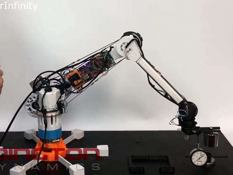
Dexter isn’t the only robotic arm in town, by any means. But in terms of hobbyist-level robotics, it’s by far the most complete robot arm that we’ve seen, and it includes a couple of design features that make both its positional accuracy and overall usability stand out above the rest. This is a robot arm with many of the bells and whistles of a hundred-thousand dollar robot, but on a couple-thousand dollar budget.
 Moreover, many of the design innovations can be taken piecemeal and used in your own project. For instance, our judges particularly liked Dexter’s clever encoder design. Optical encoders usually use a disk with holes in it; shine a light through the disk onto a sensor and you can determine the position by counting the number of resulting pulses.
Dexter takes this a step further, using the analog value of the light sensor, allowing it to track a few thousand positions per hole, multiplying the usable resolution. This means that, with a 3D printed encoder wheel and some serious math to transform this into a position, Dexter’s encoder can resolve over a million positions per revolution. That’s mind-blowing precision, and it’s available relatively cheaply due to advances in computing power.
Specifically, an FPGA and some custom “gateware” logic code runs the conversion of encoder data to arm position. That’s right, they’re dedicating an embedded Linux computer with FPGA peripherals doing the heavy lifting to calculate two joints’ position. You might think that this is overkill, but with an arm like this any small angular error in the first joint that sits on the table is multiplied by the reach of the arm. You want positional accuracy of 0.1 mm at the end of a half-meter arm, you’re looking at 0.01 degree angular resolution. Getting that resolution with a 3D-printed encoder wheel and some heavy computation is a great innovation.
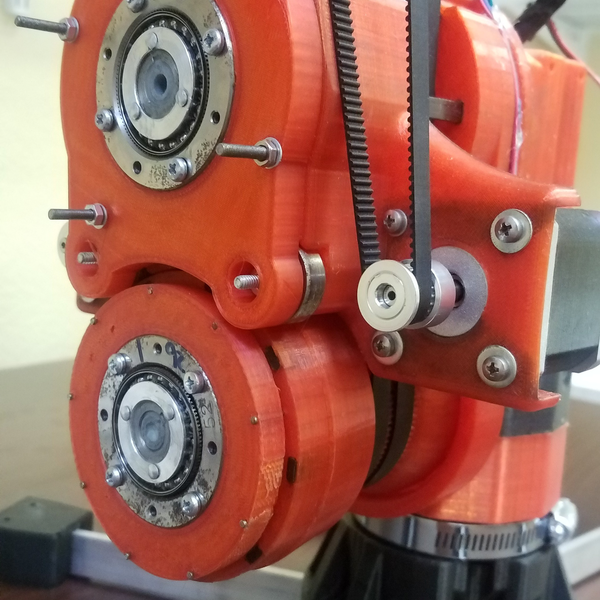 Combine such detailed positional feedback with some good software and you can design an arm that’s both compliant, strong, and easily trainable just by moving it around. Dexter uses harmonic drives for some of the axes, and while you don’t normally want to force a harmonic drive, the extreme resolution of the positional sensor lets the robot know when it’s being pushed out of position and either apply more force to hold position, or drive the motors in the direction of the motion if it’s trying to learn a new move. This makes for easy training, much in the style of Baxter, the robot that has obviously inspired Dexter, but costs significantly more and isn’t open source.
At the pointy end of the stick, Dexter has an expandable set of end effectors connected by a simple 3D-printed locking-collar-and-pogo-pin arrangement. Whether you need a vacuum, scissors, or a gripper at the end of your robot arm, Dexter has you covered.
If there’s one flaw in Dexter, it’s that the FPGA code to run the encoders was written in a proprietary hardware description language, Viva. So while the Dexter folks can provide us with a bitstream to flash into our own FPGAs, we can’t tweak the encoders’ algorithms. That’s a shame, but Haddington Dynamics’ position is that they can’t afford to re-engineer the FPGA code in order to become fully open source.
In the end, though, Dexter is significantly more than the sum of its parts. Haddington Dynamics has applied what our judge Quinn Dunki called “true hacker spirit” to making the build more affordable wherever possible, but still retaining high quality. If you’re at all interested in building a robot arm, there are a ton of lessons to learn here, and if you need a high-class solution on a hacker’s budget, this is where we’d start. We can’t wait to see what’s been updated in the newest version!
Congratulations, Dexter and Haddington Dynamics!


In before someone goes off on an “open source” project having a “proprietary binary blob”.
The source and intermediate (technically human readable) files are published. Only the compiler isn’t open source. Yet. We are working on that.
That’s awesome, James. Thank you for the reply!
This sounds like a perfect match for a crowdfund/bounty/Patreon campaign to create an OS compiler. Let those who are most interested in making it completely open source put their money where their mouth is and support your work financially. (Yes, I know you just won a big prize, but I imagine that that can be gone in a heartbeat on R&D.)
Are there any videos of Dexter in action?
https://youtu.be/PhTbzc-BqKs
Oops… sorry, wrong link. Here are the Dexter videos:
http://hdrobotic.com/videos/
Awesome, thanks!
Got to make sure you seal that encoder in a light proof dust proof box or your arm will twitch in dusty environments or changing lighting conditions. Hopefully in the “proprietary binary blob” are provisions to re-calibrate based on aging components and imperfect spacing on the encoder disk.
“Skins” are an issue and we really could use help. Right now, we have designs for skins that fit the new Dexter HD (need them for Dexter 1) and we are 3D printing them, which takes /forever/. It would be great to get some help making them via vacuform or some faster method. Our vacuform machine (purchased at Bay Area Maker Faire) was stolen, but we will probably replace it at some point. Any advice appreciated:
https://github.com/HaddingtonDynamics/Dexter/issues/4
Interestingly, that doesn’t seem to be as large a problem as one might expect. Even under flickering lights, it does quite well. The process we use is relative, comparing the light from one reading to the next, so as long as “more” or “less” light comes in as the disk moves, a bit of dust or flicker doesn’t have much effect. Also, since we are reading 5 million times a second, a momentary disturbance doesn’t really have time to cause a visible jitter. Check the videos or come see a demo.
I made a mistake in that interview at 1:08, it’s 4096, not 496. 12 bits of resolution, from black to white, then another 4096 back to black again for 8192 ticks per slit, up to 200 slits per revolution so over a million ticks per revolution. More info here:
https://github.com/HaddingtonDynamics/Dexter/wiki/Encoders
That resolution just blows me away! Bravo and congratulations to you and your team.
What would happen to the precision of the end effector positioning if the servo controls wouldn’t be running at 200 ns, but at something more modest, for example, 100 µs or 10 kHz?
The ultra fast update has several benefits
1. We can run the P term in the PID controller up and not have oscillations. Actually since it’s integrated, and the time base is so fast, the P term is less than 1, but the point is that it tracks so close that in a slower system, it would oscillate. It doesn’t have time to overshoot. And that gives us better accuracy.
2. Small perturbations in the sensor system just get swamped by the good data around them. The mechanical system filters them out because it doesn’t have time to jerk. The motor inertia starts filtering mechanically at a few kHz, but If you get the update speed up over 50 kHz the motor inductance filters out the control signals as well.
3. The position of the motor is actually being dithered around the point it needs to be. We are stepping back and forth over points in between even the microstepping points. Especially on joints 4 and 5. This is where the inductive filtering helps us.
Mainly the group delay is so low that we don’t need any filtering.
Ok cool you get these filtering benefits above 50 kHz, but the control loop is running at 5 MHz if I understand correctly, or 100 times faster than 50 kHz. How much of a slowdown could the system accept while maintaining, say, half of the total precision? Or looking in the other direction: is 5 MHz a sweet spot of some sort, or would you like to go even faster?
Really good question MvK, I’m honestly not sure of the answer. I think that part of the reason we are running that fast is that with the FPGA, “we can”. LOL. But I’m not a control theory guy. I’ve asked our lead designer and his answer was “faster is better” and he wondered why we wouldn’t go as fast as possible. So I guess that’s the question: If you can go 5 MHz, why not?
Thanks James for you quick and clear answers. Awesome project.
I got this response back from our lead about speed: “It’s a need, he decreed!” so to succeed you must heed. (ok I’ll stop now)
The sensors aren’t just feedback for the motors, they also give us a sense of touch.
Higher frequency input from the sensors on Dexters arm also gives us data about the surface we are touching. For example, we can sense ridge architecture, roughness, smoothness, etc…
This has application is quality assurance, in process testing. An FFT anaysis of the sensor data might be able to sense sound or differences in vibration. Induced vibrations can indicate internal struture and structural faults.
The encoders are quite impressive. I’m inspired to experiment with qre1113 sensors and moire patterns. https://hackaday.com/2018/03/07/0-05-mm-precision-thats-a-moire/
Thanks for reminding me of that link. I had included it (retroactively) in a page on unusual forms of encoders which I originally started for a newsletter back in 2003 :
http://techref.massmind.org/techref/new/letter/news0312.htm#Encoder
“Dexter’s encoder can resolve over a million positions per revolution. That’s mind-blowing precision” Probably should read “resolution” not “precision”.
Looks like a nifty project. Hopefully a community will spring up and iterate like what happened around 3d printers.
Has anyone got a source for these parts in Europe?
Would be also interested in that.
Yes, that would be really nice :)