There’s perhaps nothing harder to throw away than a good power supply. Whether it’s the classic “wall wart” whose mate has long since been misplaced or a beefy ATX you pulled out of a trashed computer, it always seems like there should be something you could do with these little wonders of modern power conversion. So into the parts bin it goes, where it will stay evermore. But not for the [TheRainHarvester], who figured out that the secret to putting a drawer full of old laptop chargers to use was combing them like hacker Voltron.
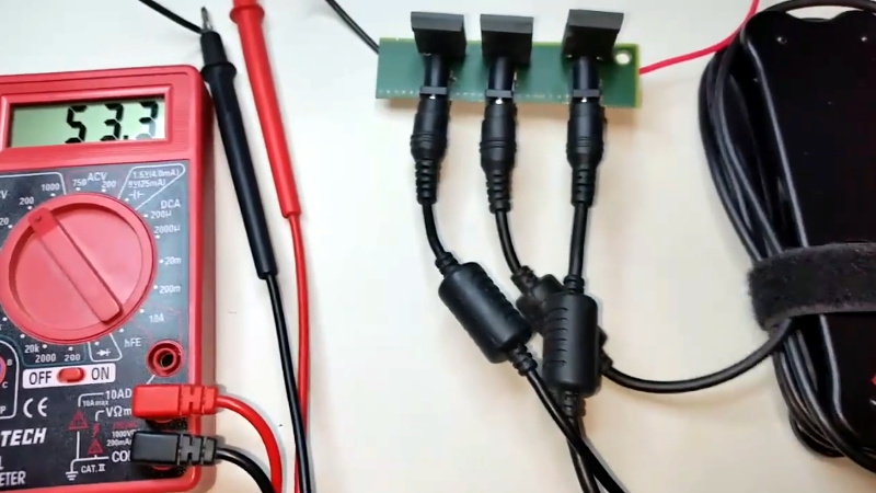
 Using three old IBM laptop chargers, he’s able to produce up to 48 volts DC at a healthy 4.5 amps. His cobbled together power supply even features an variable output, albeit with some mighty coarse adjustment. As each charger is individually rated for 16V, he can unplug one of the adapters to get 32V.
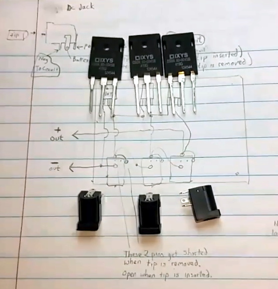
In the video after the break [TheRainHarvester] walks viewers through the construction of his simple adapter, which could easily be made with salvaged parts. Built on a trace-free piece of fiber board, the adapter consists of the three barrel jacks for the chargers and a trio of beefy Schottky diodes.
The nature of the barrel jacks (which short a pin once the plug is removed) along with the diodes allows [TheRainHarvester] to combine the output of the three adapters in series without running the risk of damaging them if for example one is left plugged into the adapter but not the wall. He’s also looking to add some status LEDs to show which chargers are powered on.
Unfortunately, [TheRainHarvester] realized a bit too late that what he thought was an inert piece of board actually had a ground plane, so he’s going to have to come up with a new way to tie the whole thing together on the next version which he says is coming now that he knows the concept seems workable.
In the meantime, if you’re thinking of hacking something together with the wealth of old laptop chargers we know are kicking around the lab, you might want to take a look at our primer for understanding all those hieroglyphs on the back of the thing.


Also worth remembering if you want somewhere around 50V from 115V AC, is the 2:1 transformers found in older PC power supplies with a 230/115V switch.
Oh, the thrift stores round here always seem to have the 24V HP printer adapters in plentiful supply if you wanna reduce the complexity to 2/3
24V HP printer adapters are typically 500 mA – 0950-3490
The inbuilt Canon ones are 42V @ 300mA.
Hoverboard chargers are 42V at 2A.
The xbox 360 power bricks are 12v 10amps or 5v 2amp.
Those 230/115V switches actually turn the input rectifier into a voltage doubler. There is no 60 Hz transformer with 2:1 windings. The circuitry is designed to put out 5 and 12 volts etc. and if you feed it with less voltage, will just try harder. Or not work at all.
If you plug a PSU into 115VAC with the switch set to 230VAC it’ll pop the fuse typically.
not if its a PSU for Weller soldering station
https://www.youtube.com/watch?v=8itTKH5tj3s
“the 2:1 transformers found in older PC power”
Good heavens. How long ago is that? Even the original PC had a switchmode supply that simply changed the arrangement of the input diodes to double (or not) the line to the 300V rail. Other than the ZX-81, the last time I saw a genuine line transformer powering a computer was an old (at the time!) S-100 system in 1985.
Oh you young whippersnappers. I had one of these that fell of the back of an Arc. Noah used if for the animal inventory database. That was an very interesting database project you know! QTY:2, QTY:2, QTY:2, QTY:2, QTY:2
:D
A have a computer PSU, that is nearly as old :-) The chips date from 1977, it is in 19″ rack module and weighing about 1kg for each of it’s 30 amps on the 5V rail :-) But it has a buttload of different voltages – 24V, +/-18V, and some more. The main part of this weight of course being the enormous ferro-resonant transformer. It has a magnetic shunt between primary and secondary and some big metal-paper resonance capacitors (10+18µF) at the secondary.
The reason for that is probably because not all voltages are electronically stabilzed, although therea are about 3-4 LM723 and a big heatsink for the 2N3501 transistors.
The transistors are 2N5301
And: Yes, there are (were) iron core computer PSUs, but I don’t expect any of this having an extra 2:1 transformer
& Extremely limited ram. :-)
My dad had an iron core PSU for a computer in his basement… it weighed over 25kg and the main transformer secondary was wound from a 3x6mm colid copper bar…
It’s very much worth noting that if you want to try this at home, make sure the outer barrel is NOT connected to line ground (earth) via the third wire. If that third lead is present, it’s almost universal that the negative side of the output is connected to it. That makes it mighty hard to connect their outputs in series.
Similarly, surplus HP server power supplies stacked need to be physically isolated from each other, and don’t connect the ground pin on one as the earth ground is tied to DC negative. They are a great, inexpensive way to get 24-30v/90A of overload protected, regulated power for about $20. No welding with them.. sorry.
I’ve used them for an RF driven CO2 laser supply, a high power hobby Li-Ion charger, and a ~700w DC 3D printer heated bed when I screwed up my wire resistance calculations. Also heated the room nicely… :)
It makes it as hard as disconnecting that 3rd prong with a 3 prong to 2 prong adapter on each one. ;)
are the diodes necessary?
Well, he made a good case for them, but I would expect the rectifiers in the supplies themselves would have been up to the task.
I just tried it with a Dell supply here, and heck, yeah, it acts like it has a diode across its output that can handle several amps (duh, ’cause it does…).
oh ok thanks
And while we are on caveats: also don’t expect it to work well if you try to parallel them for more current. They will all be slightly different output voltage, so the highest voltage one will take most of the load, while the lowest idles. The the highest poops out and lower ones take up the load until the first recovers. It makes a horrible racket. If you must do it this way, put ballast resistors in series with each, like paralleling bipolar power transistors.
If the separate PSU’s are close enough in regulation across the needed load region, it’s worth noting that the output wires will have some resistance, and that might be enough to get away without ballast resistance in some cases.
Where things fall apart is if one PSU sags more than the other at a given load point and the one that doesn’t sag takes up all of the slack until a region where the sagging PSU is barely contributing, then the question becomes “how much more of a load is the main psu absorbing, and is it over it’s standalone rating?”
Tricky to answer as shunts mess up all the measurements, hall effect current monitors are great for this though, but you have to have the +/- lines seperate, unfortunately laptop PSU’s don’t, and adding a fixture to split them apart.. induces.. more artificial resistances! :’D that again might make things seem like they are okay when they aren’t once you remove the fixture. The devil is in the details where high current and milliohms are concerned.
You could measure primary consumption with one of this cheap “energy meters”. At least with identical supplies the efficiency should be similar.
Model 2 is up on theRainHarvester ‘s YouTube channel.
Really? You know you can increase battery voltage too by stacking them.
Suitable for Hackaday? Maybe in about 15 minutes when his meter pops, perhaps in a spectacular way.
Ha Techno-trolled
It’s not a battery “until” you stack the cells.
Yes, thank you! A flock of sheep. A battery of cells.
A battery of cannon.
A dignity of canons.
You can still increase battery voltage by stacking the batteries. You cannot increase cell voltage by stacking cells. :)
Ah but there only batteries before you stack them. After you stack them is still “a” battery.
Technically, when you put two 12V Lead Acid battery in series, you actually stack batteries.
You got a whole new 12 cell worth battery of battery.