Motors are not overly complex, but this one is downright simple. Carl Bujega has been working on a motor design that heavily relies on the capabilities of the printed circuit board (PCB) fabrication processes. His talk at the 2018 Hackaday Superconference covers how he built a brushless DC motor and speed controller into a PCB. You can watch the newly published video after the break.
There are two main parts of an electric motor; the stator is stationary while the rotor spins on bearings. Electromagnetic forces are used to cause that spinning action. In this case, Carl has built the electromagnets as coils on a 4-layer circuit board (six coils on each layer). When electrified, a magnetic field is generated that pushes against the rare-earth magnets housed in the rotor.
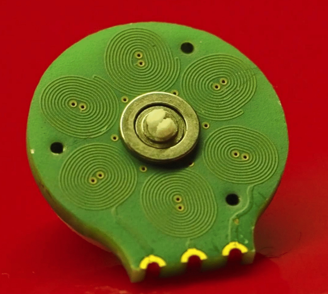 A couple of things are really interesting here. First, those coils are usually made of “magnet wire” (enamel covered wire that is very thin) wrapped around an iron core. Using the circuit board instead saves both physical space, and the time and expense of wrapping coils of wire in the traditional way. Second, Carl has been designing with manufacture in mind; you can see in the image show that his motor design is dead-simple to assemble by inserting a 3mm bearing in the PCB, inserting magnets into the plastic rotor and snapping it into place. The end goal is to make robot actuators that are part of the circuit board itself.
The genesis of this idea came from Carl’s interest in drone design, in fact, he jumped right into a drone startup immediately after finishing his EE. The company didn’t last, but his thirst for interesting designs is ongoing. When looking at reducing the total parts necessary to build a quadcopter he happened on the idea of PCB-based coils and he’s followed it to this motor design, and beyond to some very interesting flexible-PCB robot design work which you can check out on his Hackaday.io page, YouTube, and Twitter.
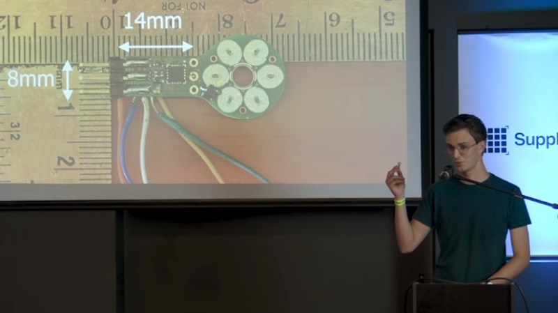
There are of course some trade-offs to this. The motor is low torque since it uses an air core and not an iron core. And he’s had trouble implementing a sensor-less Electronic Speed Controller (ESC) as the back-EMF from the coils appears to be too weak. Not to fret, he added a hall sensor and has succeeded in designing an ESC that measures just 14mm by 8mm. In fact, he’s holding up the ESC and motor in the image at the top of this article!


Borg nanoprobes are a step closer.
This reminds me of the direct-drive motors we used to find in floppydrives. Those were similar axial-flux motors, with triangular windings and a PCB as part of the stator, but there were windings of regular magnet wire glued onto that PCB.
Low back-EMF means a low torque constant (since those are the same thing). 220mA into 19 ohms gives ~4.2V, leaving only 0.8V out of the 5V supplied for the back-EMF and inductance. I’m guessing the inductance to flux coupling ratio is also pretty bad.
Making motors this was is obviously possible, but I’m guessing making a half decent motor this way isn’t. The copper fill factor of a PCB is pretty low, especially if you want to make it small, considering the track spacing is more or less constant and independent of the width of the track. You can use thick copper, but that generally requires greater spacing of the tracks, but not by much. The total PCB thickness, which is a large part of the total air gap that you’re trying to minimize.
Having magnets on both sides of the PCB, and steel rings (backiron) behind the magnets should help. Using more layers, wider tracks, thicker copper and stronger rare-earth magnets should all help. Still, I’d be surprised if it would ever supply any significant torque and be used for anything other that being an interesting display item.
So, some other commercial company has prototyped an axial bldc pankake type with the hallback magnets array axially on front and back of the motor with the stator sandwiched in-between the outer rotors of magnets. The company was claiming 15kW from 8″ x 5″ motor easily. Will update my reply if I can find it in my history.
This isn’t exactly that, but these guys are doing few kW motors based on PCB stators – nice technology story. Link: https://www.infinitumelectric.com/technology-1/
Why use copper PCB?
Coat FR4 in ferrious material and etch away. In fact, use multi layers and make lots of unique designs.
Same with ceramic, that changes shape with voltage, and many other ideas.
This design shows gross lack of understanding of physics.
That’s harsh and hard to understand, isn’t it? He already uses multilayer PCBs. Also, why would you use “ferrous” windings? Is it about making the conductivity even worse or what is the purpose?
Ferrous materials would have tremendous skin effect and practically stop the motor from turning because you can’t switch the current in.
“This design shows gross lack of understanding of physics.”
And your post perfectly illustrates why HackADay comments section is notoriously cancerous.
Think The coills should be on both sides of the Magnet. If There is The coil only on one side The flux in The airgap spreads too quickly and The Torque stays Low.
Hi. What about plating Ag onto Cu as this would help high-frequency response a lot. Also taking a few ideas from ic manufacture a possible combination would be vanadium bro ze.