Motors are not overly complex, but this one is downright simple. Carl Bujega has been working on a motor design that heavily relies on the capabilities of the printed circuit board (PCB) fabrication processes. His talk at the 2018 Hackaday Superconference covers how he built a brushless DC motor and speed controller into a PCB. You can watch the newly published video after the break.
There are two main parts of an electric motor; the stator is stationary while the rotor spins on bearings. Electromagnetic forces are used to cause that spinning action. In this case, Carl has built the electromagnets as coils on a 4-layer circuit board (six coils on each layer). When electrified, a magnetic field is generated that pushes against the rare-earth magnets housed in the rotor.
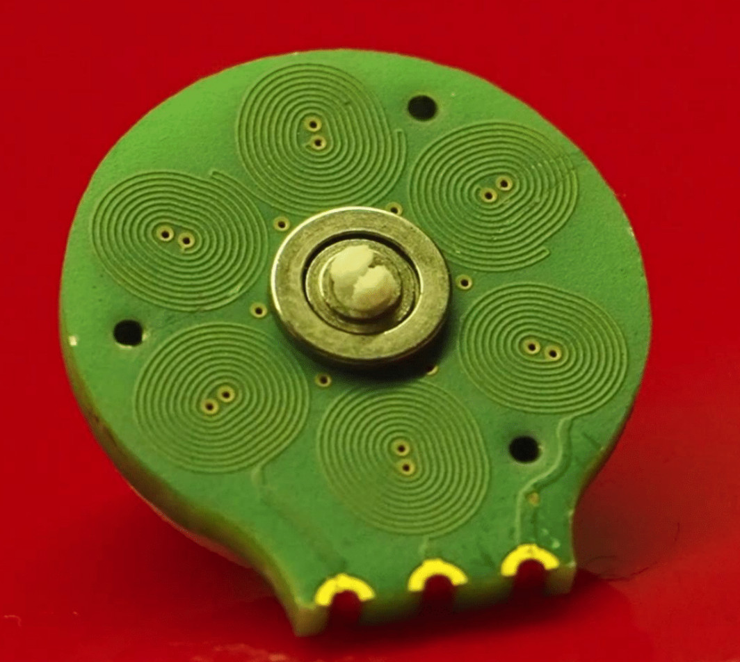 A couple of things are really interesting here. First, those coils are usually made of “magnet wire” (enamel covered wire that is very thin) wrapped around an iron core. Using the circuit board instead saves both physical space, and the time and expense of wrapping coils of wire in the traditional way. Second, Carl has been designing with manufacture in mind; you can see in the image show that his motor design is dead-simple to assemble by inserting a 3mm bearing in the PCB, inserting magnets into the plastic rotor and snapping it into place. The end goal is to make robot actuators that are part of the circuit board itself.
The genesis of this idea came from Carl’s interest in drone design, in fact, he jumped right into a drone startup immediately after finishing his EE. The company didn’t last, but his thirst for interesting designs is ongoing. When looking at reducing the total parts necessary to build a quadcopter he happened on the idea of PCB-based coils and he’s followed it to this motor design, and beyond to some very interesting flexible-PCB robot design work which you can check out on his Hackaday.io page, YouTube, and Twitter.
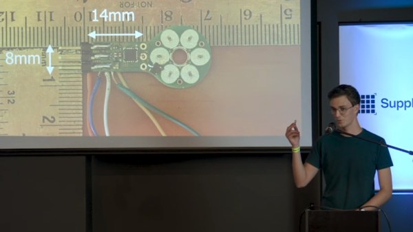
There are of course some trade-offs to this. The motor is low torque since it uses an air core and not an iron core. And he’s had trouble implementing a sensor-less Electronic Speed Controller (ESC) as the back-EMF from the coils appears to be too weak. Not to fret, he added a hall sensor and has succeeded in designing an ESC that measures just 14mm by 8mm. In fact, he’s holding up the ESC and motor in the image at the top of this article!
Continue reading “Designing Tiny Motors Right Into The Robot’s Circuit Board”


