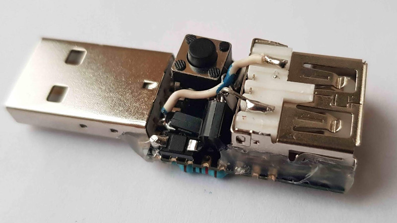
The explosion of cheap LED lighting products has given a never-ending array of opportunities for the resourceful hacker. A few dollars can secure strings of colourful illumination, but without further expenditure they lack the extra utility of electronic control. This is something that [Albert David has addressed] with his simple ESP8266-based WiFi switcher that he’s added to a string of USB-powered LEDs, and he’s neatly mounted the ESP-12 module it used atop a USB plug.
The circuitry is pretty straightforward, with only a couple of I/O lines being used. A transistor takes care of the heavy lifting, and the software comes courtesy of the Tasmota firmware for Sonoff (and similar) devices. We suspect with this economy of connection, the same task could be achieved even with the limited resources provided by the lesser ESP-01 module.
There was a time not so long ago when performing a task such as controlling a light over a wireless network involved significant cost, power, and complexity. In the nearly five years since we reported on the arrival of the ESP8266 we have progressed to the point at which that task is a simple project using commodity components, and that represents something of a miracle.


Neat! For bonus points, do the same with WS28XX RGB LED strings, then you can turn them on, off, any colour of the rainbow, or make seasonally-appropriate patterns dance along (regardless of the season) :-)
nice 3D construction. I would have use a MOSFET however to get rid of the voltage drop of the transistor (but maybe that’s good because it will allow the LED strip to last longer?).
That transistor is turned on pretty solidly; I doubt there’s significant C-E voltage when on.
I’m always weary when people insist on gluing/fixing grounded metal the back of PCB antennas. Sure it’ll probably still work, but surely it reduces the output power and sensitivity?
Maybe, or it may work even better. Difficult to say, but indeed a risk he took.
I look at this and I first think: wifi and a 32-bit processor to turn a string of LEDs on and off?
Then I realize: less than $10 in parts and a couple of hours to build and flash…. why not?? These ARE interesting times…
Me too, thought at first i wasn’t sure if it was used just for on/off or also for making animations.
I spent <$2 on this, $1.5 ESP-12F and remaining 50cents on other components. Of course 1hour of soldering/assembly work is the most expensive part if you consider DIY is not fun :-)
I’d love to see a 12v version of this. I’ve been searching for something simple for a while, but don’t have the skill to DIY.
It wouldn’t be much different, just instead of two diodes use LM1117-3.3 (with two caps) to provide 3.3v to ESP8266, and that’s it. For extra lazy solution just keep adding diodes in series until you get 3.3v suitable for ESP. Also replace USB connectors with terminal posts, it’s not a good idea to have USB connector that gives 12v without any negotiation, as it will surely fry something before or later.
Love these projects with the 8266! However, I am no wiz and struggle all the time with trying to bring my ideas to life. Things that are simple to, probably most of you, and hard for me. I keep plugging along though and value the information out there. Thanks to all!
keep at it!
Actually the lesser module would be the ESP8285, which doesn’t include the 3M flash module and has only 1M builtin, which should be plenty for these features. It’s quite sad they are not cheaper. Quite a bit smaller though.
Actually the lesser module would be the ESP8285, which doesn’t include the 3M flash module and has only 1M builtin, which should be plenty for these features. It’s quite sad they are not cheaper. Quite a bit smaller though.
Did we just uncover your two accounts? Slavko?
busted
@Jflissar if you want a quick start using the (cheaper) ESP8285 (mentioned in the thread above), to control WS2811-compatible addressable LEDs (also mentioned in the thread above) you could source parts as documented at https://vgkits.org/blog/projects/rainbow/ even programming them in a python interpreter which runs directly on the board. I’ve put these free resources together to support people like yourself who are getting started, and welcome feedback.
I’ve spent a lot of time with the ESP8266 and have many projects around the house with them, it’s one of my favorite boards. I’m still at the basic level though and have been trying to teach myself as I go! There is so much information out there along with tons of different products, I’m just trying to keep up.
At the other end of the scale, these 2metre by 2metre 16-segment character displays were hand-built from WS2811 addressable LED elements using ESP8266 as wireless LED drivers, controlled by a Raspberry Pi for urban messaging from the windows of a tower block https://twitter.com/vgkits/status/958310116234809344
I have a 12V RGB string that is controlled by Alexa using an ESP-01.
What I love best about this project is how small it is an yet the creator has still managed to sneak in a through hole resistor when an probably could have done the trick. Definitely a hack.
…when an SMT probably could have done the trick.
Through-hole resistor is intentional, i wanted a 10k resistor directly connected between EN and VCC pin. With smd resistor, i would have to use an extra wire to reach the VCC point which more soldering work and more items. I did several iterations of this design to optimize the work and items involved – may be someone can further optimize it :-)