Inexpensive OLED displays with I2C interfaces abound, but there is a catch: they tend to be stuck on I2C address 0x3C. Some have a jumper or solder pads to select an alternate (usually 0x3D), but they lack any other method. Since an I2C bus expects every device to have a unique address, this limits the number of displays per bus to one (or two, at best.) That is all still true, but what [Larry Bank] discovered is a way to get multiple OLED displays working with considerably fewer microcontroller pins than usually needed.
While bit-banging I2C to host one display per bus on the same microcontroller, an idea occurred to him. The I2C start signal requires both clock (SCL) and data (SDA) to be brought low together, but what would happen if the displays shared a single clock line? To be clear, each OLED would — logically speaking — still be on its own I2C bus with its own data line, but they would share a clock signal. Would a shared clock cause attached devices to activate unintentionally?
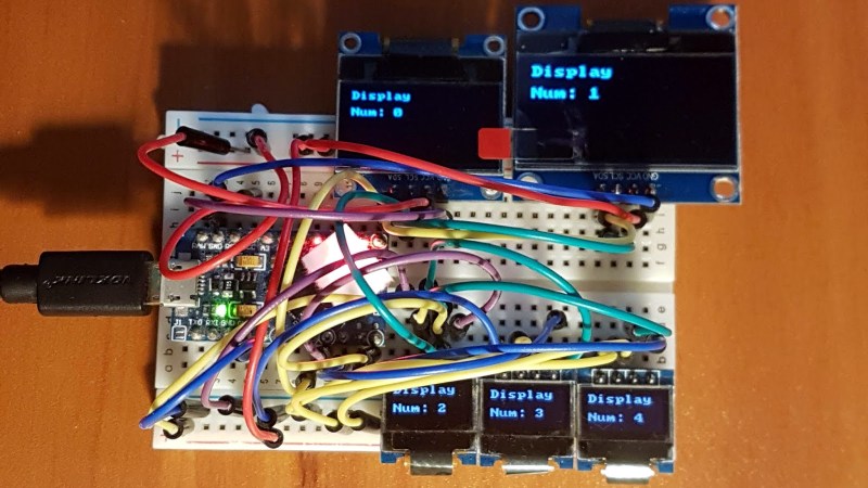
A quick test consisting of four OLED displays (all with address 0x3C) showed that it was indeed possible to address each display with no interference if they shared a clock. Those four individually controlled displays needed only five I/O lines (four SDA, one shared SCL) instead of eight. The Multi_OLED library is available on GitHub, and in case it is useful for devices other than OLED displays, bit-banged I2C with support for shared clock lines is available separately.
There’s more to do with OLEDs than get clever with signals: check out these slick number-change animations, and that even looks to be a project that could benefit from a few saved GPIO pins, since it uses one small display per digit.


Alternatively, you put all on the same bus as per usual, but mux them by toggling the address pin – keep then all on one address (eg $3D), but change the address pin of the one you want to talk to at that moment (only ever speak to $3C). Though this does take one more pin than OP’s method
Or use analog multiplexer to talk to multiple devices. There are 1-of-16 analog MUXes controlled by 4 pins, which can be connected to binary 4-bit counter making it possible to address and control 16 devices with 3 pins and using hardware I2C interface.
Excellent idea. This is the way that makes more intuitive “sense” to me.
Even better! But it needs an additional part
It means “to cheat” because you add external hardware. If to cheat is allowed, you can add an external micro controller (just 1 wire to pilote it in serial) to have lets say 32 DO. The real trick is to do “more with less” and move from 8 to 5 necessary pins is that.
It is a neat approach with only a minor amount of fiddling.
I did a byte similar approach primarily for speed circa 2001/2 with ramtron frams to get an effective 8 times the single chip bandwidth ie. Instead of purchasing back then a single higher speed non fram chip (with lower retention specs & availability) I got 8 off 400khz rated 10 million cycle ramtron frams sharing a common (buffered) SCL with one byte port (which was bit addressable 8051) such that each fram got one SDA bit off that same port – firmware managed the address/handshaking. So once initiated the CPU output or read one byte at a time effectively multiplying the ramtron’s bandwidth by almost 8 to approx 3.1Mbytes/sec. Of course it was over 8 devices so took up more space, could do something similar if need be with 8 displays these days off the one suitable CPU as vector messenger (if you like) to manage all displays with it also running of a serial link or even just wifi – perhaps even with some touch feedback too. Depending how you perceive costings for the product you also get 8 times the memory. Thanks for post, good reminder.
Cheers
Reading this I got an idea: If I am not mistaking, three bit-banged lines could be used to form three I2C buses used one at a time, by using same lines as SDA in one bus and as SCL in another.
One of the three lines must be kept steady high during communication, and it is another line for each bus.
This principle could be applied to more than three lines.
In other words, I2C buses could be charlieplexed (sort of).
(Sorry for replying to myself)
Three combinations of two out of three without repetition:
ab, ac, bc
Three buses with three lines, a, b, and c:
a SDA
b SCL
c HIGH
a HIGH
b SDA
c SCL
a SCL
b HIGH
c SDA
Six combinations of two out of four without repetition:
ab, ac, ad, bc, bd, cd
Six buses with four lines, a, b, c, and d:
a SDA
b SCL
c HIGH
d HIGH
a SDA
b HIGH
c SCL
d HIGH
a SDA
b HIGH
c HIGH
d SCL
a HIGH
b SDA
c SCL
d HIGH
a HIGH
b SDA
c HIGH
d SCL
a HIGH
b HIGH
c SDA
d SCL
etc.
or just use a TCA9548. 8-Channel I2C Switch, and no extra IO or bit bang.
Except that the TCA9548 is more expensive than the ATMEGA MCU in use here. If you are short of pins then the analog demux approach works (a 74HC4052 demuxing the SCL line to one of 4 I2C devices, all sharing the same SDA should give you 4 independent devices with only 4 pins total), for a cost of about £0.80 in lots of one. Otherwise this way is essentially cost free (beyond the MCU).
I’m not all that experienced yet so maybe there are good reasons not to do what I am thinking but I don’t know. The first thing that comes to my mind is not to share the clock line but rather to share the data lines and feed each LED with a “separate” clock. I would only do this if there are no more than a few LEDs to control. After that I am thinking I would have one clock line from the microcontroler splitting off to a bunch of and-gates. The other inputs of the and gates would be the outputs of a counter chip. The outputs of the AND gates of course would end up being the clock lines for the individual LEDs. That way you only need the normal 3 pins plus a 4th to cycle the counter.
This is great if you prefer the mediocrity of bit bang I2C.
I ran a project a number of years ago with a Propeller reading 11 Sensirion SHT11 Temp/Humidity sensors (that use a protocol similar to I²C). I ended up using one data line for each and then one unique clock line for all and it worked flawlessly. It output a graphic of my house showing temps for every room through composite video to my TV. All I needed to do was flip the TV input to “AV” and I could see the data.
Did you have secondary problems with the long runs of wire for this?
Better explanation:
SDA transitioning low during SCL high (inactive) is a start condition, hence sharing the SCL with a dedicated SDA works: no start condition if SDA held high.
I have a similar problem and want to string 4 OLEDs on the same bus. I found a YT video from 2014 where there are jumpers to extend the addressing (0x3C etc) but the little 0.96″ display of today that I have doesn’t have jumpers but DOES have 2 SMD resistors marked R3 & R4, maybe jumpers for the LSBs of the address register
Could anyone care to comment on the possibility that removing R3 & R4 creates additial unique addresses at 0x3D, 0x3E, 0X3F ?? Don’t want to waste 5€ a shot with a wasteful experiment?
NB I found a video on YT where the guy seemd to do just this, but spoke of “changing” the resistor rather than removing , he did seem to resolder a different resistor
Very cool !
Check out this concept how to use the HW module of teh ESP32 with its IO_MUX capability which would even avoid doing bit baning :-)
https://hackaday.io/page/21183-hacking-esp32-multiplexing-i2c