We can make our 3D-printed parts even more capable when we start mixing them with some essential “mechanical vitamins.” By combining prints with screws, nuts, fasteners, and pins, we get a rich ecosystem for mechanism-making with capabilities beyond what we could simply print alone.
Today I’d like to share some tips on one of my favorite functional 3D-printing techniques: adding heat-set inserts. As someone who’s been installing them into plastic parts for years manually, I think many guides overlook some process details crucial to getting consistent results.
Make no mistake; there are a handful of insert guides already out there [1, 2]. (In fact, I encourage you to look there first for a good jump-start.) Over the years though, I’ve added my own finishing move (nothing exotic or difficult) which I call the Plate-Press Technique that gives me a major boost in consistency.
Join me below as I fill in the knowledge gaps (and some literal ones too) to send you back to the lab equipped with a technique that will give you perfectly-seated inserts every time.
Heat-Set Insert “Theory”
Heat-set inserts are stock parts that add threads to a part made from a thermoplastic. Since 3D-printing relies on oozing plastic out of nozzles, literally every single 3D-printed material fits the definition for thermoplastic–so they’ll all work! As far as matching techniques go, it’s almost like these inserts were made for each other! (Alas; they weren’t, but thankfully injection-molding plastic has made these parts a commodity.)
Heat-set inserts work by softening the surrounding material as they’re being installed. Once installed, removing the heat-source causes this molten plastic to re-solidify around the inserts’ knurled feature, holding it in place. Let’s consider thinking about this process in terms of heat transfer. Installation holes are smaller than the inserts themselves (they’re undersized), so we can’t install inserts by hand force. Rather, we first heat the insert and then conduct that heat into the surrounding material such that the hole deforms, accommodating the larger shape of the insert.
As more time elapses, heat transfers from the insertion tool, through the insert from surface area contact, and finally outwards into our 3D-printed part, where it dissipates. The longer time spent inserting the part, the more time the heat has to travel into the part where it can deform the surrounding part areas. In large scale manufacturing, this process is done by machine. In our case, though, we’re installing by hand, so we’ll need to keep our timing in mind. Finally, don’t forget that when we install the insert, we’re displacing molten plastic to make space for the heat-set insert. That displaced plastic needs to go somewhere, and it usually ends up mushed at the bottom of the insert.
There’s a Tool for That
Our tools need not be expensive. I use an insert “installation tip” combined with a budget 40W soldering iron from Amazon without any temperature control. These “installation tips” aren’t particularly special, but, unlike soldering iron tips, they aren’t tapered. Using a tip without a taper makes it easy to remove the tip once the insert is installed.
You can find inserts on McMaster-Carr (pn: 92160a115) or on Tindie. (I admit that I use the McMaster-Carr one for 4-40 and M2.5 inserts, but also with M3, M4, and M5 inserts without any issues!)
I strongly discourage using a vanilla soldering iron tip for the following reason. Most of these tips are tapered. If we use a tapered soldering iron tip, we risk getting the iron tip stuck in the insert. Remember: metal expands when it heats up and contracts when it cools. As we install the metal insert into the printed part, we’re dissipating heat from the insert into the part, causing the heated insert to cool slightly and also contract around the iron tip. The net result is that when we try to pull the iron tip out, the insert comes with it! I imagine that this scenario is akin to a Chinese finger trap.
All that said, this problem wouldn’t happen too often for me back when I used a vanilla soldering iron tip for this process, but 1-out-of-5 ruined prints was enough for me to scrounge up the extra $10 and get the right tip.
Finally, my last tool for this process is a small square of thin sheet-metal, about 150x150mm (6″x6″). This sheet becomes a “flat” reference that I’ll discuss in the process later.
Designing for Inserts:
When it comes to sizing holes for inserts, I’d recommend following the dimensional info that comes with the insert datasheets. As a quick reference, here’s a mini compendium of links for some of my go-to inserts and their hole size recommendations.
- UD-43030 short M3x0.5 insert (relevant dimensions, vendor)
- 94180A331 M3x0.5 tapered insert (relevant dimensions and vendor)
- 93365A120 #4-40 tapered insert (relevant dimensions and vendor)
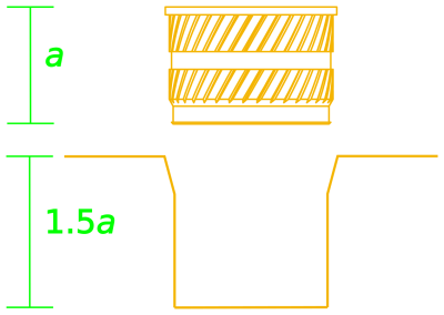
To accommodate displaced material, I suggest increasing the hole depth by about 50% of the insert length. This change ensures that the displaced plastic has somewhere to go and doesn’t fill up the cavity where the insert should be.
Other guides suggest adding a small taper to the hole feature. This is a nifty feature that enables inserts to seat themselves into the hole before installing them with heat. Some inserts are themselves tapered, which has the same seating effect on an un-tapered hole. Adding this tapered feature (or buying the slightly-more-expensive tapered inserts) isn’t necessary, but it does make the installation process easier.
Slicer Settings:
With a design ready-to-go, I’d recommend tweaking one 3D-printer Slicer setting first, namely the perimeter layers. Slic3r defaults to two perimeter layers for hole features. I’d recommend bumping this value up to at least 4 perimeters for two reasons.
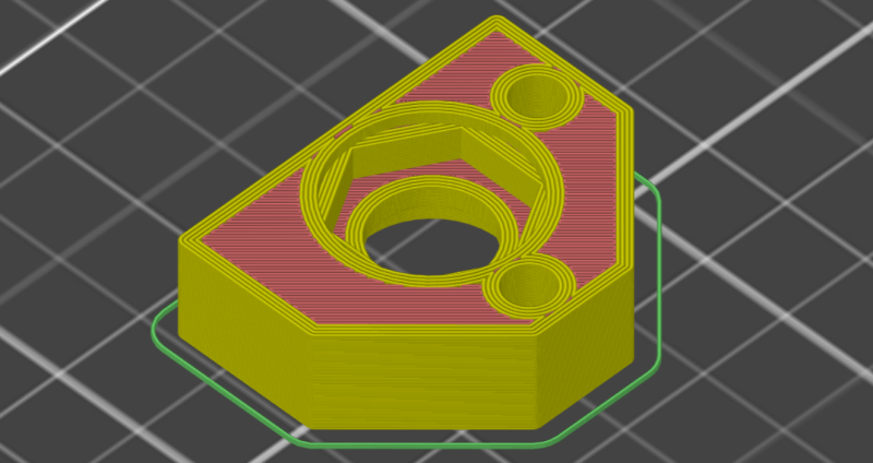
First, we want to make sure that our installed insert is still “grabbing” onto material after we install it. An installed insert displaces material outwards during installation, so adding layers improves the odds that we haven’t melted through it upon installation.
Second, adding more perimeter layers also reduces the extent to which external indentations form on the part when inserts are situated close to the external surface of a part. These indentations are called sink marks, and they’re actually a common problem found in injection-molded parts too. Sink marks occur because a part contracts as it cools. I’ve discovered that adding more perimeters reduces this effect. I can’t say for sure why this is the case, but my best guess is that adding solid material reduces the free space inside the part, making it more difficult for internal geometries to change shape.
The Installation Process and the Plate-Press Technique:
Now that we’ve got a handle on designing and prepping parts for inserts, let’s get to the installation procedure.
First, make sure that your soldering iron has completely reached its set temperature before using it to install inserts. If we try installing an insert while the iron is still rising to its setpoint, the process just takes longer, and all that heat from the iron is spending more time diffusing into our part, causing it to warp.
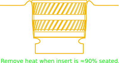
Next, with the insert positioned in the hole, apply heat to the insert. Let the weight of the soldering iron tool itself apply the gentle force needed to push the insert into position. Gravity should be doing most of the work here. This process takes about 10-15 seconds. Keep applying heat until your insert is about 90% seated into your part.
Ok, here’s where we derail from convention. With the insert at about 90% into you part, remove the iron and quickly flip the part onto a flat, heat-resistant surface and gently push the part down until it seats flush with the material. (I use a small piece of sheet metal for this step.) Wait about 6-10 more seconds for the part to cool, and you’re done! I’ll call this maneuver the plate-press technique.
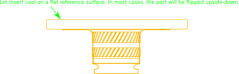
This final step of the process seems odd, but it’s critical for two reasons. First, it seats the insert so that it’s both vertical and completely flush with the top of the printed part. Second, it flattens any bulging material that flared up while we were installing the insert.
Results
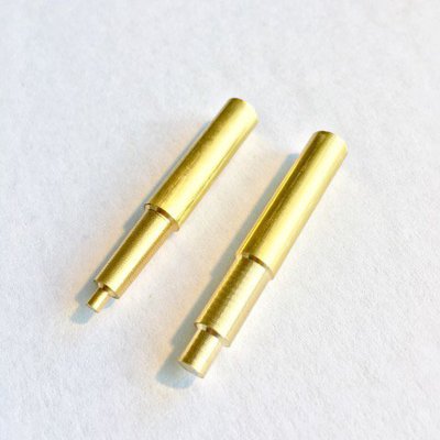
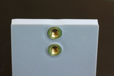
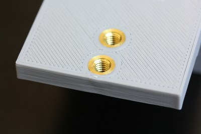
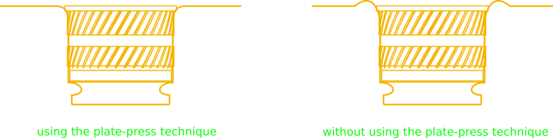
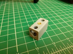
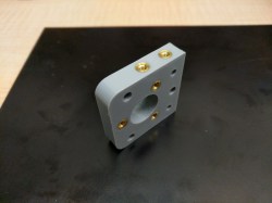
If all went well, you should have a nice-looking insert that’s flush with the part surface. In the image below, I used the iron to seat these parts most-of-the-way in and then cooled them flush with the plate-press technique.
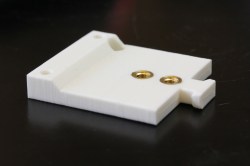
In the next example below, this insert was set without using the plate-press technique. Notice that nasty “bulge” of excess material that beads up around the insert. That’s precisely the bulge that we can remove when we use the final plate-press technique.
Reflection:
I imagine that tweaking both our iron temperature and insertion speed might reduce or eliminate this bulging effect if we practice installing these inserts under various conditions. But that hypothetical need for practice is exactly what makes the plate-press technique so valuable. Simply put, the plate-press technique gives us consistent results without the need for robot-levels-of-precision. We simply “smoosh” the insert into its final place and be done with it. The result is a flush insert with little effort and no practice. Admittedly, this technique is not how the industry folk do it for mass-production, but it sure is consistent — a hack even.
Conclusion:
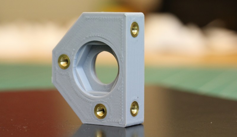
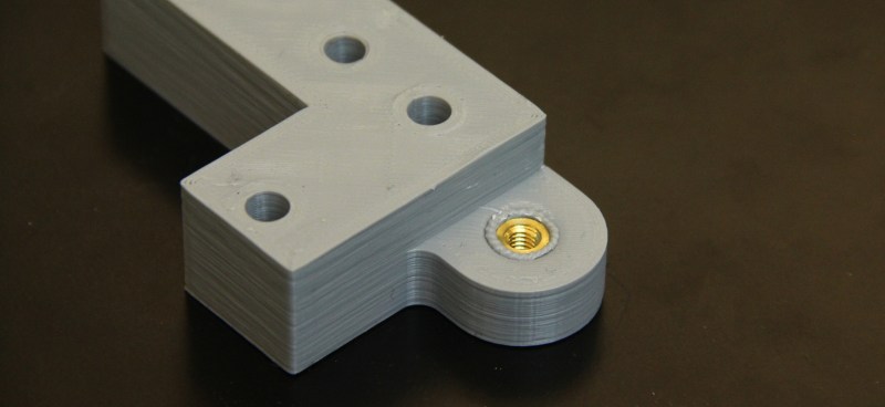
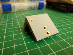
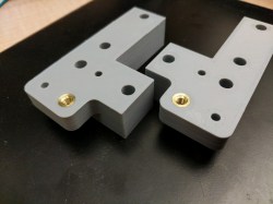
That’s it! I hope this guide serves you well in nailing beautiful flush inserts every time without too much hand hassle. Here’s a quick snippet of a few other parts I made to put some perspective on what to expect.

I’ve started posting my wares up with #beautifulinserts, and I’d love to see how this technique fares for you. If you make anything fun, why not inspire some fellow community members by joining the conversation?


Indeedee dodee, nice post wanted to do variants of these things many times mostly got heavily sidetracked when more serious $ work stuff turned up, thanks for post :-)
In most cases I just print some pilot holes and cut threads into them with a cheap thread cutter.
Works much better than I had expected.
Yeah that is what I do for stuff that I don’t have to take apart a lot. Works great.
Also more reliable against pull-out than the inserts.
Those I glue into place with 2K glue.
umm what do you do if the insert pulls out hypothetically on a hypothetical laptop shell and you hypothetically dont have the cash to replace your hypothetical top shell would some hypothetical super glue work this is all hypothetical of course
You don’t even need a tap for M2 and M3 cap screws in PLA. Just twist the cap screw in with considerable force into a tap sized hole. The result may be a stronger connection.
Which is basically what a Roll / Form tap does :)
Great idea, those look really good. Another idea might be to use a small drill press (not turning) with the right size pin installed in the chuck and heat the pin while pushing down as if you were drilling. This might give you a good “feel” for how fast to go at a given temperature. In other words, just use the drill press as a press and heat the pin using induction or just a small torch. Your plate method might still be needed though…that really gives your parts a nice, neat finished look.
A bit embarassing as this is what I did with many abs commercial enclosures 30 odd years back when fitting odd things to cheapest cases yet still having strength once all cooled down, occasionally this included using two inserts screwed to the bolt with a bit of solder to hold the inserts together of course with more drilling in the plastic first. This resulted in a deeper hole with the two inserts offering greater strength than one. Ie using the soldering iron on head of screw whilst pushing it into place down with pliers…
“literally every single 3D-printed material fits the definition for thermoplastic”
That’s not really true. It’s true for Plastic FDM 3D printers, but not for resin printers for example.
Anyway that’s a great technique and I’ll use it for my next experiments! Thanks for the idea
Curious where everyone gets their inserts from. I’ve bought from McMaster Carr, but they seem expensive for what you get. https://www.mcmaster.com/heat-set-inserts
They’re only mildly more expensive than what you’d pay for brass nuts of any kind. It looks like Amazon has some decent import variety packs for cheap, but I imagine that the tolerances are a little wider, but then FDM isn’t ultra repeatable to the 0.001mm, so it’ll probably work out fine.
just go to ebay and search for brass insert. takes a while from china but cheap.
I rip mine out of a stash of old DSL modems. Each modem has about 20 of them.
Nicely written! I’ve been using this method for a while now, but mostly eyeballing it. I’d also like to point out to Noel Rubin, who has done a great deal of work documenting it on his Instagram : https://www.instagram.com/p/BqdS-bPHo9K/
The flat plate technique is a good one. Up until now I’ve been trimming away the excess fat with an xacto.
Also, with a drill and a file you can turn down old soldering iron tips for this purpose.
I’ve inserted 1000s of these with a regular soldering iron tip with no issues. Never thought of getting the actual insertion tip. They look simple enough to turn on a lathe though.
The flat reference surface is an excellent tip, I have been using a bastard file to remove the bulge of melted plastic, thanks!
It’d probably be easy to get some cheap soldering iron tips and turn them on a lathe to a more appropriate shape.
That’d be a no-no for actual soldering but ought to be fine for this.
It might even be feasible to use a drill press and a file or Dremel.
How about making a hotend to hold and heat the insertion tool. This would allow for much more precise placement, temperature control and insertion speed. :)
Now this is a great idea!
Technique also keeps them perpendicular to the main body of material. Of note could one use the threaded part of the insert as both a means of force (insert movement), control (depth, alignment), and heat transference?
I have used these quite a bit, using just forceps, a butane torch, canned air, and a bolt that matches the threads. Screw the bolt in by just a few threads. Heat the bolt with a torch until the brass insert is hot, sink the bolt/insert into the surface until almost flush, remove the bolt. The canned air is useful if you want to cool the area quickly.
This might not be suitable for assembly-line production but it’s been working well for short-run projects.
I’ve been planning on using helicoils in printed parts, easier to assemble, lets you put holes closer to the edge of a part, and should be strong enough for most purposes. The main problem is that I can’t find any chinese knockoff bottoming taps.
I’ve found that it is fairly hard to design around thermoset inserts since you basically need 10mm of material on every side of a m3 hole.
We used to make our own bottoming taps by just grinding the end down on a regular tap. Be careful not to get it too hot when grinding. This way, you can have a cheap full tap and a cheap bottom tap for not much invested.
Great technique. Do you have a general rule of thumb for a delta on the diameter of the threaded insert compared to that of the hole in the 3d print for that insert? For example, if the diameter of the threaded insert is 4mm, then what diameter would you make the hole for that insert in the 3D print?
I’ve been using inserts that I picked up from ebay, which came with a small data sheet (well, a sticker on the outside of the baggie). It lists the hole diameter to use, and that’s exactly the diameter I set in my 3D model. It seems to work fine.
If yours don’t have a stated diameter on the packet, I’d try to measure the outside diameter of the insert without the sticking out barbs (I’m not sure exactly what the correct term is) and use that as your hole diameter.
So, in your example, if the total OD of the insert is 4mm, but the barbs stick out 0.1mm on each side, then make the hole 3.8mm.
One issue with the soldering iron inserts is finding one that works with your iron. I have a fairly common weller iron and the exact special insert tips mentioned in the article won’t work with my iron. What I did was buy a cheap tip assortment for my iron which had a couple of tips that were really short/stubby. Works quite well.
Other thing on the hole depth is you need to leave room for your iron tip on the other side. Even if you use the special insert tip there needs to be clearance. If that’s not possible I’ve been successful with putting the insert on the end of a screw, holding the screw/insert with pliers and using a heat gun to heat the entire assembly. You have to be careful when pushing down but with a steady hand it can work well.
Threaded inserts (triserts) https://www.mcmaster.com/triserts have worked very well for me and don’t require a soldering iron. You don’t need the fancy installation tool if you use a matching screw with two nuts to drive it, then back off the bottom nut. They install into unthreaded blind or through holes and cut their own threads as you drive them.
I agree 100% and have done the same many times. There are also press-in varieties that do not require heat, but I’ve found they don’t have as much bite as the threaded OD inserts mentioned above.
Also if installing 4-40 or smaller inserts, you run the risk of snapping the screw-converted-to-install tool if you use a stainless screw (which I always have an abundance of). Mild steel is much less brittle and therefore a lot more forgiving when used to install inserts.
Wow how do they get away with that price for the install too, its essentially just a nut and a bolt.
I’ve noticed this, the more rarified the (mostly University based) education and also not limited to just focus on ever higher performance semiconductors, then the loss of appreciation of fundamental fabrication techniques or even basic manufacturing practices of value for earlier 100 yrs such that those habituated to high end expensive tech easily acclimatized to paying that many extra donero for dead simple stuff that those most in their early 50’s can readily generate in their workshops…
Apparently it also generates a lot of words to say, generally older is better.
Back in the day, around ’81, this technique was used in the Heathkit H19 case. Worked very well.
I love using inserts, but for hacky tests and for when screws won’t be removed, screwing into the plastic can be satisfactory.
As others have suggested, just tapping the print or screwing right into it to cut threads with a screw can do the trick.
You can also take a screw, line it up in an undersized hole, and apply a soldering iron to the tip. When the plastic starts to soften from the heat (you can feel it), press the screw in and step away :) The cooling plastic will tighten around the screw and make a remarkably solid connection. Takes some practice, I like this for screwing PCB’s into cases: I press the screws in with the board there and sometimes never remove them.
Just use self tapping screws. They use them a lot in products made of plastic.
i have about 10 pounds of coarse threaded plastic screws that i use for connecting 3d printed parts. inserts are kind of an unnecessary extravagance. they hold pretty well unless you overtorque.
i always engineer for pull-through stresses, so a regular nut set into a depression (no heat) works fine for me. do these inserts really have any strength against pull-out stress? even professionally-done inserts (like in the laptop i’m using right now) tend to pull-out pretty easily — i’ve had to replace 7 of 10 inserts in the hinge assembly with longer screws and regular nuts in a pull-through configuration. i don’t really see the advantage.
i think the main advantage is reversibility. you can disassemble and reassemble them repeatedly with much less wear. my plastic screws can be removed and replaced only so many times before the holes wear out. nuts and bolts work ok for reversibility but they likely are not a good choice for precise fitting. if you want to build something you are going to take apart and put together a lot, like a jig for mass production, then inserts are a good choice. usually when i put 2 subassemblies together i don’t intend to take them apart very often or at all. so plastic screws salvaged from junk are what i use.
I would say a JIG needs bolts (opened often), inserts are for laptops (opened only few times during it’s life) and a crappy vacuum cleaner cover can be screwed straight into the plastic (not opened).
Instead of having a deeper hole for the moved material, why not take profit of what 3D printing allows and design a 45° taper on the last few mm of the hole? It would take the excess material in it and allows the insert to bottom out and be constrained in that direction.
I suspect the plate technique also helps by cooling the top layers of plastic quickly, fixing their shape as well as cooling the insert itself
I would love to see a comparison of the holding strength for an insert vs a trapped nut vs screwing directly into an undersized hole in the plastic (length of bolt would obviously make a different here as well)
Sam
I know this is old, but Stefan at CNC Kitchen did this!
https://youtu.be/2wRc1KbEAU8
My friend Noel has built several jigs to set his inserts and they all look amazing :)
https://www.instagram.com/p/BqdS-bPHo9K/
That is a pretty sweet setup. Nice work Noel!
For the most part, using the ‘thread’ option in F360 is more than adequate. Inserts are so 5 years ago!! The author of this article needs to get with the times ;)
Helicoil and Kato thread inserts. Used primarily in the aerospace industry. Print the thread. screw in the insert and you have the strongest threaded hole. I do it on my mark2 every week.
any pics or documentation on what sized threads are best to design or how to design them?
I don’t have a lathe… And wanted something quickly to try out a while back. My findings.. you can easily convert a soldering tip using a normal drill press and a hand file while it spins. You want a loose fit so it doesn’t need to be precision made. If you print your hole exactly perimeter width smaller than the insert it holds well and doesn’t form any bulge. Underneath, leave some spare space. For bonus marks, from time to time you might drag molten plastic back through the thread. Because of this, leave another section of clear area underneath to accommodate using a tap screw to retap the thread. I’ve saved a handful of prints this way when I was first getting the feel for it.
I just use screws designed for thermoplastics. Usually i make the hole tight enough, and maybe preheat the screw a little before inserting. Rock solid connection for most applications. Of course, threaded inserts have an application for me, but only when a screw is required that will constantly get loosened/tightened.
The one thing I don’t like about those is they’re brass. Besides the fact they might or might not have lead in them if they’ve been machined, it’s softer than steel and it makes me worry that a steel bolt will chew it completely up.
What I am interested in is rivet nuts. Either installed the usual way very carefully, or with the aid of epoxy. Mine get here tomorrow so I’ll know then!
Hmm really ?
Pray tell what plastics might you consider using either routinely or sporadically that will so firmly retain the brass insert beyond the steel screw’s applied torque (in what environment too ?) that might risk stripping the brass thread – I would really like to know And whether these (possibly torlon like plastics it seems) can be used reliably on any 3d printer with appropriate commercial sources of filaments hopefully readily available ?
I’m not concerned with stripping the thread, I’m concerned with wear from the steel being harder than brass, plus cross threading from hurried setup in the field, and wear from random grit and crap that decides to get in.
FWIW, I tried the rivnuts, they seem to work decently, I guess I’ll know in a few months how well they hold up against creep and PLA cracking.
I use a screw threaded through the insert, held in a pair of pliers. Heat it up on a gas flame and push it in. Unthread the screw and heat it up again if you need to push further.
Would the spatula that every FDM printer owner already has work in place of the sheet metal? It seems like it’d be easy just to press that down on the part.
I’m doing something that mounts to a tripod.
Any recommendations for a 3D printed part to accomodate the 1/4-20 bolt from the tripod.
I’ve just been undersizing and tapping, but I’m open to suggestions.
Here’s a Youtube video where CNC Kitchen compared all the brass inserts (both the cheap and expensive ones) & just threading the bolt directly into the plastic and shows the tensile strength, pull out resistance, etc
https://www.youtube.com/watch?v=G-UF4tv3Hvc
And it is interesting that the same YouTube channel does comparative pull out tests on a threaded hole, inserted hole, and pocketed or base fitted nut. The last is the strongest, with the only advantage of an insert being that it allows better dismantlement as in reality the shear area for a tapped thread and an insert are the same.
Thanks dude!
Thanks so much! This was invaluable
Adorei o artigo, bastante esclarecedor e didatico. Obrigado por compartilhar sua experiencia conosco.