
This is an exciting day for me — we finally get to build some ham radio gear! To me, building gear is the big attraction of amateur radio as a hobby. Sure, it’s cool to buy a radio, even a cheap one, and be able to hit a repeater that you think is unreachable. Or on the other end of the money spectrum, using a Yaesu or Kenwood HF rig with a linear amp and big beam antenna to work someone in Antartica must be pretty cool, too. But neither of those feats require much in the way of electronics knowledge or skill, and at the end of the day, that’s why I got into amateur radio in the first place — to learn more about electronics.
To get my homebrewer’s feet wet, I chose perhaps the simplest of ham radio projects: dummy loads. Every ham eventually needs a dummy load, which is basically a circuit that looks like an antenna to a transmitter but dissipates the energy as heat instead of radiating it an appreciable distance. They allow operators to test gear and make adjustments while staying legal on emission. Al Williams covered the basics of dummy loads a few years back in case you need a little more background.
We’ll be building two dummy loads: a lower-power one specifically for my handy talkies (HTs) will be the subject of this article, while a bigger, oil-filled “cantenna” load for use with higher power transmitters will follow. Neither of my designs is original, of course; borrowing circuits from other hams is expected, after all. But I did put my own twist on each, and you should do the same thing. These builds are covered in depth on my Hackaday.io page, but join me below for the gist on a good one: the L’il Dummy.
L’il Dummy
As Al points out in the article linked above, a dummy load is just a resistive element that matches the characteristic impedance of the transmitter’s antenna connection. In almost every case, that’s going to be 50 ohms. The reason that the load needs to be as resistive as possible is that it needs to continue looking like a flat 50-ohm load no matter what frequency is applied to it. Any inductive or capacitive elements in the load will make it more reactive, changing the impedance as the input frequency changes. This could lead to RF power getting reflected back into the final amplifier transistors in the transmitter, possibly damaging them or destroying them altogether. Not what you’re looking for.
That means our resistive elements need to be as non-inductive as possible. But, they also need to be able to dissipate a lot of power. The HT dummy load, which I’ve dubbed L’il Dummy, needs to handle the 5 to perhaps 8 watts an HT can output. Trouble is, power resistors in that range are often wirewound, and a coil of wire will have too much inductance. We’ll need to be clever in sourcing components.
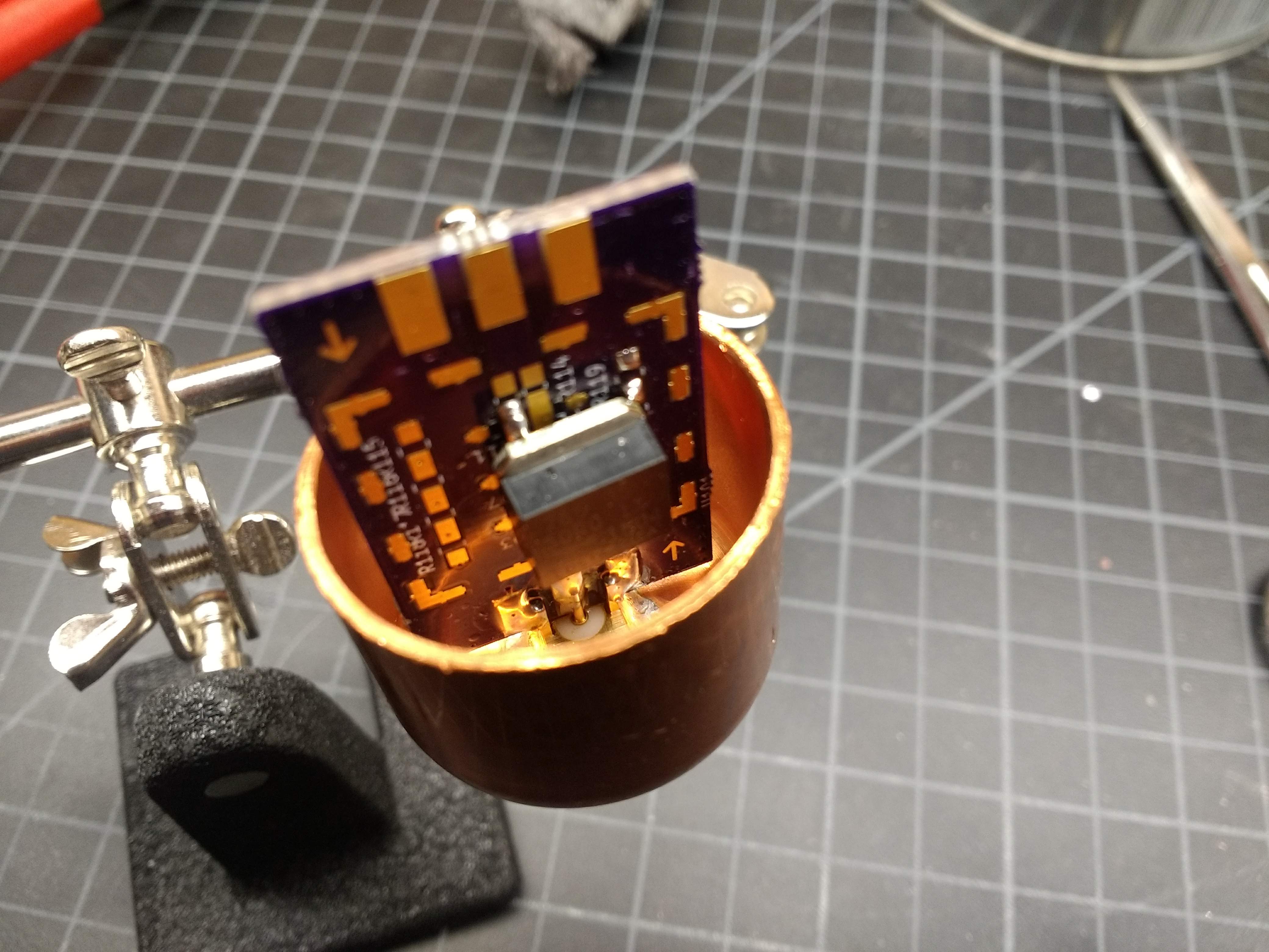
The circuit for L’il Dummy is hardly worth a schematic – it’s just an SMA jack with a 50-ohm resistor across the outer ground and the inner conductor. I chose to build the circuit on an RF Biscuit board. This is an open-source design that enables all kinds of handy little RF circuits — attenuators, filters, and as in this case, dummy loads. The resistive element I chose was a thick-film SMT device capable of dissipating 35 watts – way more than enough for this job. That and an edge-mount SMA jack should have been all I needed to make a working dummy load.
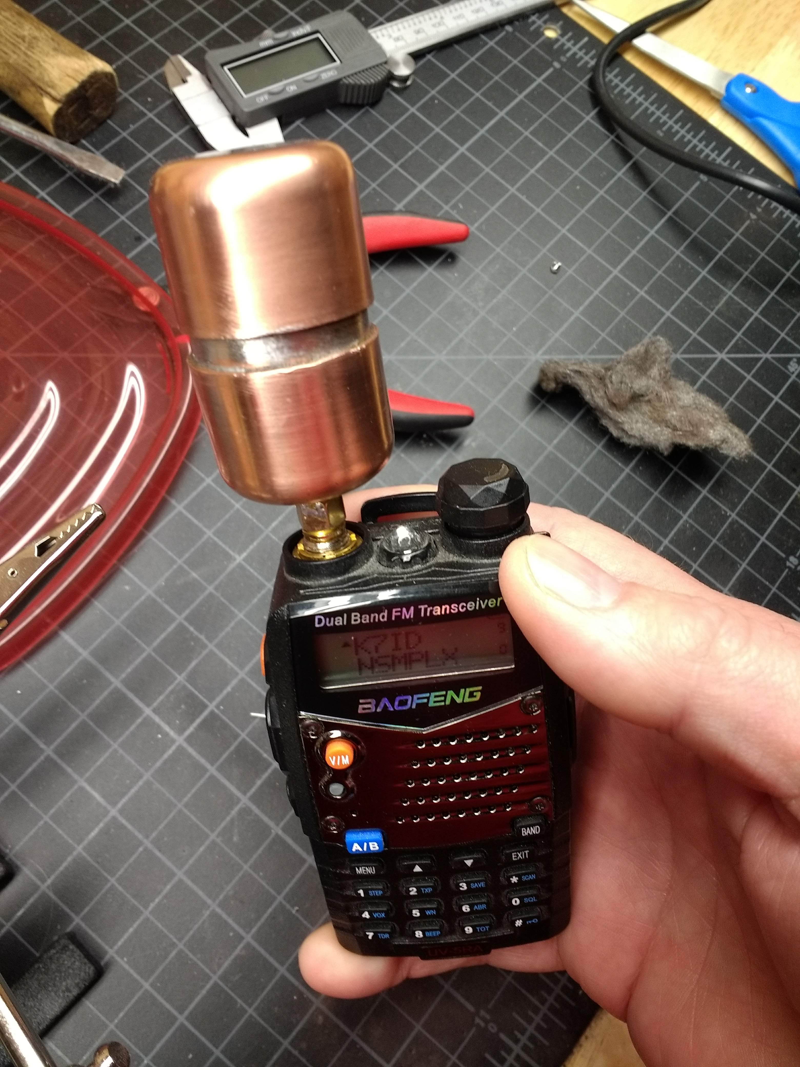
To my surprise, once I soldered the resistor to the RF Biscuit board, the dummy load was almost as good an antenna as the stock rubber ducky on my Baofeng HT. I was able to hit a local repeater through the dummy load without any issues. Clearly not a good design. To correct it, I put the whole thing into an enclosure made from 1″ copper pipe. Not cheap stuff, but not too bad, and I like the look of polished copper. Soldering the whole case together was a challenge that my big Weller soldering gun wasn’t up to, and trying to get everything heated up enough with a propane torch without overdoing the heat was a fun time.
Testing on a Budget
Now for the $50 question: does it work? I tested the resistance with a DMM and it comes out to just about 49 ohms, which is close enough in my book. But that’s DC resistance; what about impedance? I don’t have an antenna analyzer, so I trolled around and found a simple method for measuring impedance with only a function generator and an oscilloscope. My scope has a 20-MHz function generator built in, so I whipped up a quick test jig from a BNC jack and an SMA jack, connected in series through a leftover 1000-ohm resistor.
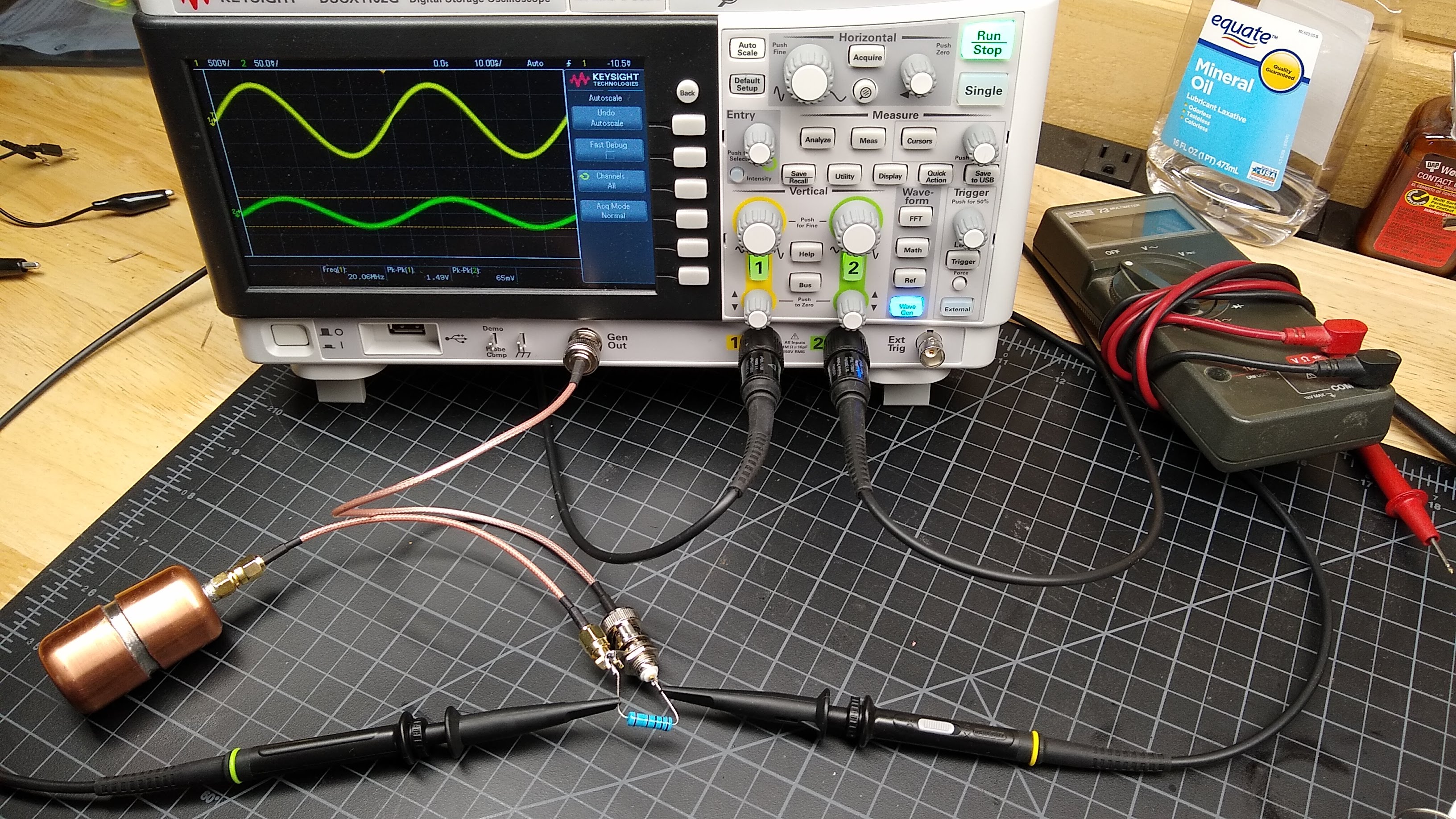
Applying a sine wave into the dummy load, measuring peak-to-peak voltages on each side of the resistance, and doing a little math is all that’s needed to characterize the impedance from 2.5 MHz to 20 MHz. The math is simple:
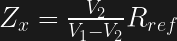
with V1 being the voltage across the input, V2 being the voltage across the output, and Rref being the actual value of the series resistance, which I measured at 998 Ohms.
And the results are pretty close to 50 Ohms, and flat across the tested band
| f (MHz) | V1 (V p-p) | V2 (V p-p) | Z (ohms) |
|---|---|---|---|
| 20.0 | 1.49 | 0.062 | 43.3 |
| 15.0 | 1.89 | 0.082 | 45.3 |
| 10.0 | 2.57 | 0.113 | 45.9 |
| 5.0 | 3.90 | 0.173 | 46.3 |
| 2.5 | 4.70 | 0.217 | 48.3 |
I wish I could measure it at VHF and UHF frequencies, but that will have to wait until I get a function generator that goes up to 400 MHz or so. I doubt very much that a $50 budget would cover that, though.
Next Time
I had intended to cover both L’il Dummy and its bigger, somewhat smarter brother in one article, but I still have some testing to do on Big Dummy. I’ll cover that next time, and after that we’ll move onto measuring the output of a cheap Chinese HT and perhaps building a filter to clean it up.


I doubt that resistor would handle 35 watts without the heatsink tab connected to anything..
Slap a small heatsink, and dunk it into a paintcant full of mineral oil, you’re good to a few hundred.
Excellent project!
My only suggestion would be to add a short pigtail between the HT and the dummy load to reduce mechanical stress on the BNC connectors, if it can be done without changing the characteristics of the load.
I think it looks heavier than it is. A good whip antenna will put more mechanical stress on the BNC connector than this dummy load will put on. Just don’t use the can like a handle and swing the radio around your head..
Instructions unclear, radio now sticking out of the wall.
Yeah, it really isn’t that heavy. And if I damage a $25 radio…
… then you would have to fix it or buy another $25 radio. Why not deal with it first?
This could be oil filled too. Drill a 3/16″ hole in the end and solder on a 10-32 nut over the hole. Add mineral oil with a syringe (leaving a small air space for expansion and insert a small screw with teflon plumber’s tape on the threads to seal it.
Honestly, I thought of that but chickened out. I’m not sure how the RF Biscuit is oriented inside the case, and I fear drilling into it. I should have drilled and tapped the top cap before soldering. And I’m not 100% convinced my solder joints are liquid-tight, nor that the SMA jack itself is. That would be a mess.
Yeah, the SMA isn’t going to be liquid tight on the center conductor. Bit good thought.
In Army Radio School they used a 100W (incandescent) light bulb for a demonstration.
Later, one of the instructors told me it was to allow nearby receivers to pick up the signal, while still dissipating most of the signal in heat/light. IIRC, it was a 45W FM transceiver.
If you don’t have an oscilloscope/function generator, is there another $50 method to testing the impedance?
Pay someone $50 to test it?
I found a couple of Funky Generators in a dumpster once,
and was given an o-scope. (I gave away an o-scope once too)
Those fit in under the $50 benchmark.
B^)
That’s a good question. I would think that since you want to know if the impedance is flat over a range of RF frequencies, you’d have to at least have something that can generate a signal. What about the radio itself? It’s basically a sine wave generator, right? As long as you don’t modulate it, of course. And it’s even programmable across a wide range of frequencies.
You’d have to come up with a way of measuring the voltage drop of a high frequency alternating current, though, and that might not be easy with an affordable DMM. Most of those tend to fall off in accuracy above 10 kHz or so.
https://www.youtube.com/watch?v=ue0wtlrmCJE
I’ll have to poke around and see if I can come up with anything.
Use an SWR meter. It should be 1:1 SWR at the frequencies you want to measure. Any reflected power is an indication of an impedance mismatch. The math to figure out the impedance is left as an exercise to the reader.
The proper way (which can still be done for < $50) id to measure the forward and reflected power with something a touch more sensitive than a cheap SWR meter. Get a directional coupler for the freq range you wish to measure, put it inline with the dummy load, measure the transmitted power. Reverse it (or use a dual coupler), measure the reflected power, apply same math as before.
The coupler can be store bought or made with copper clad board, a razor knife, a schottky diode, and some resistors/caps. Heck, you could even add an Arduino, an OLED, automate the whole mess, and still be below $50.
For just verifying it’s well matched, you could probably do the usual SWR (standing-wave-ratio) test that one uses for antenna tuning. There are various cheap ways to do that, and it’s a very useful measurement method for hams anyway.
I found this method in a nutsvolts article:
https://www.nutsvolts.com/magazine/article/a_low_cost_rf_impedance_analyzer
I’ve been given more than one oscilloscope (two) for free before and bought more than one for really cheap… just have to keep an eye out for great deals, free items, ham fests, clean outs, passing on equipment for gets trashed, etc. Shopgoodwill.com has em on also and not just eBay for great prices also. Craigslist, Offerup and Letgo are my typical venues when I need a test equipment fix for some Made in the U.S.A. devices.
DDS function generators are cheap and there are cheap modules also on eBay with even ones around $100 to $300 to get up to 16GHz and I’ve read that some of the cheaper new oscilloscopes aren’t bad either. I have a wavetek 142HF and HP8460 OPT323 I picked up for great deals on eBay… though have look at, have in my watch/wish list or bought some of the below.
e.g.
AD9850
SI5351
ADF4351
ADF5355
AD9959
AD9854
AD9834
https://www.ebay.com/itm/10MHz-15GHz-Handheld-Smart-Singnal-Generator-Frequency-RF-source-Sweep-oled/173645888770
LMX2595
For a simple not the best SWR method… you can try this method:
https://www.rtl-sdr.com/rtl-sdr-tutorial-measuring-filter-characteristics-and-antenna-vswr-with-an-rtl-sdr-and-noise-source/
I also have been working on microwave projects and studying the electronics requirements which is making me realize one of the reasons for the 0603 and smaller components and micro sized world of electronics… so there isn’t so many issues with microwave and higher frequencies traditional electronics design methods. Anywho… I thought this instructable was interesting and somewhat relevant and maybe even worth an article:
https://www.instructables.com/id/23GHz-SMA-Calibration-Kit/
There is this project also that has been morphed into modules that sparked my attention for a cost effective way to study also and potentially use the modules for other projects if wanted and/or later build your own more effective design:
https://groups.io/g/SoftwareControlledHamRadio/topic/29533629
https://groups.io/g/HBTE/topics
https://github.com/erikkaashoek/Tapr-VNA/tree/master/Doc
The last thought I had in the above post got me thinking also about the above modules like the power modules referenced in the three links and I guess if wanting really sensitive measurements a AD630 lock-in amp module or other DIY design used for testing a range of frequencies can be used.
https://www.holographyforum.org/data/pdf/aa-Collection_a_k/aa-Laser/aa-lockin/Homebrew_lockin_amplifier.html
Then also thinking about making an oscilloscope with the modules instead of a spectrum analyzer. Have to think about using the software in the time domain versus the frequency domain and proper modules or components to hack together a cost effective higher frequency range oscilloscope.
HHhmmm… there are electronic device methods solely to make the measurements without software also and without readout screens even, thinking dial instruments and/or standard precision tolerance components.
Uhmm… I guess this method might be easier:
https://wiki.brown.edu/confluence/download/attachments/1162769/IMPEDANCE%20BRIDGE.pdf?version=1&modificationDate=1438363137000&api=v2
This is a neat document I have and found again at this link:
https://www.scribd.com/document/77583930/A-History-of-Z-Measurement
This gets more complicated:
http://ws680.nist.gov/publication/get_pdf.cfm?pub_id=4720
Then this came up as an interesting library edition to have a copy of that is way beyond me still:
https://literature.cdn.keysight.com/litweb/pdf/5950-3000.pdf
It looks pretty nice but I’m not sure about the choice of connectors. Sure, it screws right onto your ht and looks convenient plus cute there. But besides taking a picture for this article when would you want to connect a dummy load directly to an ht?
Most of the time you are going to want some measurements. I don’t think I have seen wattmeters with those SMA (or is that reverse SMA) connectors on them. Or maybe you will want to connect it to a homebrew transmitter. SMA is kind of small and hard to work with isn’t it? Most homebrew stuff I have seen is either BNC or SO-23. (if it even uses a connector at all!)
Stay tuned for Part 2, wherein we build Big Dummy, a more capable dummy load with a proper SO-239 connector and test points for making measurements.
Be sure to give credit to Red Foxx,
for popularizing the phrase “Big Dummy!”
B^)
BNC is like the worst RF connector ever. SMA (not RP-SMA) is pretty much standard for industrial RF use with the N type connector as an alternative where more beefy connectors/cables are preferred.
The worst?!?! Really?!?!
I take it you never dealt with PL/SO-239? It doesn’t even have a guaranteed impedance! And yet most non-handheld ham or cb gear uses it. What do you think of twinlead going to screw terminals w/ or w/o spade lugs? That has seen a lot of use as an RF connector. I’ve even seen cheap radio transceivers that used RCA phono plugs or headphone jacks!
But yes, in industry (for most values of industry) it’s been all SMA & N for the last couple of decades.
SMA is very small though. It might not be very friendly for non-professionals, especially ones with older eyes or fatter fingers. Also if this is a connector for coax it pretty much mandates tiny coax. Sure, if you are considering SMA for a transmitted signal you are probably talking low power where a skinny wire isn’t going to melt. Loss is going to be huge though for cables that skinny of any significant length. And if it is for any of those reasons you chose to go with N… great! Now you have a connector that is frigging huge! Welcome to the opposite extreme!
So don’t get me wrong. I’m not trying to tear down SMA or N. SMA is great for internal connections, especially with hard line. N is great when you are going to move some power or your connector is also the physical support at the base of your antenna. There needs to be a middle ground though and the best one I know of is BNC.
Have been doing cellphone development for a decade until recently. SMA and N are pretty much the only connectors used on test equipment in that segment, but for the end product they are huge. Check the tiny coax and connectors used inside modern smartphones if you want to see small connectors :-D
Even the absurdly cheap SMA stuff (like attenuators) from China are pretty reliable. Compared with BNC which tend to be unreliable, too loose or tight or even fall apart from normal use. This comes down to the bits and pieces for a BNC being die cast in cheap materials whereas SMA are machined from better (machin-able) materials
“This comes down to the bits and pieces for a BNC being die cast in cheap materials whereas SMA are machined from better (machin-able) materials”
No, it’s because the BNC connector’s design means it can’t transfer strain well – it’s only constrained by the two pins (well, and the actual ground connection, but that’s why it’s not reliable). SMA/N connectors screw on, so they can transfer strain well. You can buy die-cast SMA and N connectors too.
“SMA is very small though. It might not be very friendly for non-professionals, especially ones with older eyes or fatter fingers. Also if this is a connector for coax it pretty much mandates tiny coax.”
Yeah, um, no. You can get coax as thick as LMR-400 with SMA ends, and that’s the best you can do with BNC as well. The limitation isn’t the *size* of the connector, it’s its rigidity, and while an SMA connector may be smaller, since it’s screw-threaded it’s *more* rigid than a BNC. LMR400 is actually thicker than the SMA connector itself. Anything bigger would break either a BNC or SMA connector, which is why you need N.
“There needs to be a middle ground though and the best one I know of is BNC.”
The middle ground between SMA and N is TNC, not BNC. BNC’s only advantage over SMA or TNC is ease of use. TNC has better shielding and better rigidity so it works for higher frequencies, higher power, and thicker cable. But you don’t gain a lot going from SMA to TNC, which is why those are the two most common connectors.
For every connector there is a purpose.
BNC has a place. SMA has a place. N has a place. 7/16 has a place, And even UHF has a place.
Each has it’s own characteristics, strengths and weaknesses. BNC is good to a KW and about 2GHz. SMA far less power but good to ~18GHz (~32GHz for some variants). N is good to 18GHz and a few KW. 7/16 is good for many KW at Many Many Hz. etc.
UHF is a legacy, but one that is here to stay. Like which side of the road you drive on.
I’ve connected a dummy load directly to an HT on several occasions, when testing and debugging stuff that connects to the HT’s mic connector and is supposed to make the HT transmit. An APRS TNC is an example of such a device. I don’t want my tests to be transmitted to nearby hams, but I don’t mind a little leakage that lets me hear the signal on a receiver within a few feet of the transmitter.
SO239/PL-259 would be appropriate for this purpose. That’s what you’ll be feeding into with any bench radios.
As usually, China have you covered.. E.g.
https://s.click.aliexpress.com/e/zz65wwG
However, I would go for e.g. a 40dB power attenuator and a small dummy load so you have the possibility to use the gear for measurements too.
That link is broken for me, but I suspect it’s one of those little dummy loads that for for a couple of bucks. But that’s not really homebrewing, is it?
Yeah. Just some random DC-3GHz 10W dummy load with SMA for about $11. There are plenty of that stuff. But right, not the same as hacking stuff together. Not that I see much point about a whilw article on attaching a resistor to an SMA connector in a rather poor way.
Second hand BNC connector, soldered into the top of a metal ‘sample’ paint tin. Bunch of 5W wire wound ceramic resistors in parallel(To increase power and decrease inductance), (Something like 10 or 15?) with the initial value selected to give a finial value of 50 ohms.. And a 100:1 resistive tap to a SMA connector on to one side for sampling(Most useful feature! combined with a RTLSDR you can look at your spectrum without putting it on the air!).
Very flat across HF and most of VHF, can handle 100W for 10 seconds, more with oil I’m sure.
Made it quite a few years back so don’t remember the details, but it was made with junk box bits and worked surprisingly well.
(If you have enough of them, any sane resistor value works, you just parallel them to get your final 50 ohms)
You almost exactly described Big Dummy, the subject of the next installment.
“In almost every case, that’s going to be 50 ohms.”
Sure. That’s the value you will need the most. But why stop there?
I built all of these: http://www.ad5x.com/images/Articles/PrecisionMismatches.pdf
They are various purposely mismatched dummy loads that are good for testing your swr meter.
I used them when I built this: http://ludens.cl/Electron/swr/swr.html
Fun times!
That’s a good point – it’s nice to have “known bad” to make sure your test gear is working.
Mineral Oil?
That’s for constipation, not for electrical work!
If you are going to make an oil filled load then do it right. Use something that is actually made for the job just like the good Lord intended. There is only one thing that goes inside MY dummy loads. Good o’l polychlorinated biphenyl! I still have a couple of drums of Aroclor 1234 and one of 1115 back behind the tool shed that I rescued when the old GE plant shut down. I use it in ALL my hot radio gear. Nothing else works like it!
Right next to your drum of Freon contact cleaner, I’ll bet. Keeping contacts clean and suntans a deep bronze since the 1950s…
QRP dummy loads also lend themselves to smd soldering practice/projects
http://vk5hse.blogspot.com/2013/03/50-ohm-smd-dummy-load-prototype.html
I’ve got a couple of those Baofeng radios. Cheap, they do what they do. I refuse to put a radio in my Mustang, so I have one of those in the glove box…just in case.
Why? Can’t you just slap a heatsink on a $2 terminator? Rhetorical question, yes you can. It can’t take the load for continuous operation, but neither can your HT.