
The basic 16×2 LCD is an extremely popular component that we’ve seen used in more projects than we could possibly count. Part of that is because modern microcontrollers make it so easy to work with; if you’ve got an I2C variant of the display, it only takes four wires to drive it. That puts printing a line of text on one of these LCDs a step or two above blinking an LED on a digital pin on the hierarchy of beginner’s electronics projects.
 What’s that? Even four wires is too many? In that case, you might be interested in this hack from [Vinod] which shows how you can drive the classic 16×2 with data and power on the same pair of wires. You’ll still need a microcontroller “backpack” for the LCD to interpret the modulated voltage, but if you’ve got an application for a simple remote display, this is definitely worth checking out.
The basic idea is to “blink” the 5 V line so quick that a capacitor on the LCD side can float the electronics over the dips in voltage. As long as one of the pins of the microcontroller is connected to the 5 V line before the capacitor, it will be able to pick up when the line goes low. With a high enough data rate and a large enough capacitor as a buffer, you’re well on the way to encoding your data to be displayed.
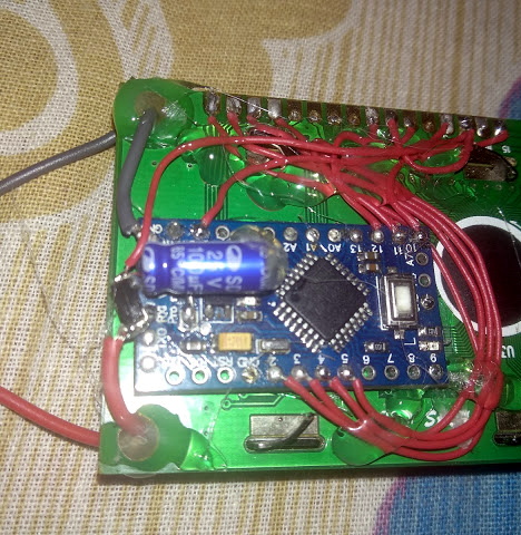
For the transmitting side, [Vinod] is using a Python script on his computer that’s sending out the text for the LCD over a standard USB to UART converter. That’s fed into a small circuit put together on a scrap of perfboard that triggers a MOSFET off of the UART TX line.
We actually covered the theory behind this technique years ago, but it’s always interesting to see somebody put together a real-world example. There might not be too many practical uses for this trick in the era of dirt-cheap microcontrollers bristling with I/O, but it might make a fun gag at your hackerspace.


It’s like 1-Wire protocol for higher-power devices. Quite interesting…
Not too far from what has been done for year with the DCC protocol on model trains. Clever thinking however to apply it to the classic 1602 LCD
And slot cars
Earlier model trains and slot cars used an analog protocol to control motor speed.
Lego Dacta sensors too.
This is not just for a fun gag and has real world applications.
For example if you want to add functionality to your doorbel, and the wiring is hard to modify and you only have 2 wires available.
For reliable applications over long wires I would prefer another scheme though. Something equally simple is to put a LM7805 in front of your uC (With an LC filter because of the long antenna wires) and then modulate the supply voltage between 12V and 17V. With a 12V zener and a pull-down resistor on an uC pin you then can already switch the uC pin between 0V and 5V. (Add a bit more components for protection. Long wires always need that).
Other common applications are when supply voltages are modulated by video or audio. Microphones with 2 wires have been common for a long time. LNB’s get power over the coax cable too.
Hmm, if anyone has even a little design/investigation experience with the age old reliable classic 4-20mA industrial sensor interface then this article might well tickle many types of augmentations including perhaps obverse types of secure signal multiplexing beyond simple current feedback with barest minimum of (copper) cabling, thanks for post provoking furious note writing for some distant future ;-)
In fact, if the price of processed sand continues to drop whilst processor power continues we could well observe the low conductor asymptote arise sooner ie. Power with RF signalling at many levels too on the barest minimum copper needed along with solar and thermal power scavenging too…
Cheers
Neat idea, and fun implementation, but hardly new. Around 1980 our company was supplying backend (radio) communications support for an Israeli company (whose name escapes me) that did this for irrigation equipment: They used a single pair of wires, carrying low voltage AC power to control valves, read sensors and various similar SCADA tasks, over farm-size territory. The protocol was polarity-agnostic: In the field you just vampire-tapped your device into the twisted pair wherever. My recollection was that the modulation was not particularly complex or fast: maybe just amplitude modulation of the AC power. I remember asking “Why AC”: everything was transformer isolated, so no ground loops, and better lightning protection.
(another one)
If you want the wires to be interchangable, a bridge rectumfire at the end is the simplest solution for DC power, and you might as well start with AC.
AC also has much less to no Electrolyses problems, and when cables get damaged and a bit wet in the field then AC improves reliability.
I don’t know what modulation was used, but AM / FM modulation of a signal in a few KHz range seems a logical and simple choice. A bit similar to X10 maybe.
Rectumfire? Too much chilli?
Glad I wasn’t eating or drinking when that word entered my brain.
…and now we know that AvE’s first name is ‘Paul’. :grin:
Coincidentally, I just happened to see an older post (in search results, trying to find an unrelated post that I thought existed but apparently doesn’t) that says his name is Chris.
Reminds me HART protocol, digital signal overimposed to 4-20 mA analog signal, multiple devices on the bus
Maybe not new but somebody had to do it. And the comments are already almost more interesting than the article.
Now make it bidirectional.
This is similar to how the Lego Mindstorms RCX works (maybe others?), depending on the sensor.
To read, it would charge for 3mS, then read for 100uS.
So I guess using (enhanced?) Manchester encoding, or some request for data, the end point could return data by using high/low impedance.
the power companies have done this for years
AFAIK, it’s more of a tone/pulse during zero-crossing, than DC modulation.