If you want to take a long exposure photograph, you need a tripod to hold your camera steady. But a tripod won’t help when the ground it’s standing on is moving. That’s exactly the problem [Emvilza] ran into when he wanted to take minutes or hours long photographs of the night sky. His solution was to build a barn door tracker, which he carefully documented in both English and Spanish.
Barn door trackers, also known as scotch mounts have been used by photographers for many years to cancel out the rotation of the earth. This causes stars to appear frozen in the sky and allows for photographs of very dim celestial objects. These trackers range from simple hand-cranked affairs to complex mechanical creations. [Emvilza] decided to have a go at designing and building his own tracker, using only basic tools, as he didn’t have access to a CNC or 3D printer.
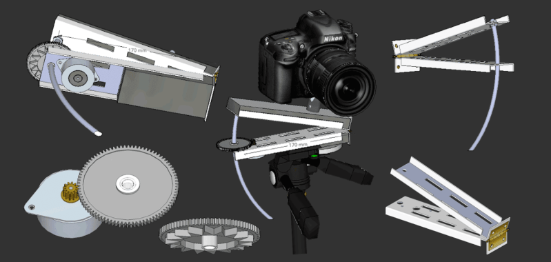
The tracker itself is built from wood, with metal hardware. [Emvilza] spent a ton of time designing the tracker using SketchUp. The carefully drawn plans ensured everything would fit together and operate correctly.
One of the toughest parts was accurately bending a threaded rod enough to make it work with the tracker, but not bind the drive system. The mount’s motion comes from a threaded rod. The rod is driven by a stepper motor. Control and sensing is handled by an ATmega328 programmed using the Arduino toolchain. [Emvilza] learned Eagle and designed a PCB. Rather than etch a board, he simply built the circuit on perfboard, following his layout and traces.
The end result is a tracker that looks and performs great — just check out the images on [Emvilza’s] site to see some examples. Not only that, [Emvilza’s] well written documentation will help anyone looking to build a tracker in the future!


I do not get it… Why bend the rod at all? Wouldn’t a straight rod with a hingle be simpler?
If he were to use a straight rod, the position where the end of that rod makes contact with the upper portion of the rig would vary over time as the hinge opend. That point is the pressure point / contact point which moves, or opens, the rig. If that position changes, then the corresponding amount on movement per turn would also vary. I suppose one could work up a solution in the software to account for this, but I am guessing that is why he went for the curved rod.
Not a difficult software task, but it requires positive knowledge of position for the compensation. For shorter exposures (a few minutes), a constant rate is ok, if the proper rate is used, but for longer exposures, the rate must be properly compensated during the run, as well, to avoid blurring.
These days with DSLR’s used in so much astronomy, I think exposure are only 30 seconds to 2 minutes. The threaded rod makes me think about a 3D printed gear segment for a moment arm.
I have a Canon t4i – Manual settings and “bulb mode” – the shutter will stay open as long as the battery lasts, or if it’s plugged into USB for power, indefinitely.
The position does not need to change:
https://www.nutsvolts.com/uploads/wygwam/NV_0115_Wierenga_Figure_1.jpg
But this still needs some corrections due to changes in alignment.
I’m sure there are thousands of ways to build it, but I was simply trying to point out that in *this particular case* where the drive is direct and the advancement of the threaded rod goes through both parts of the hinge, he most likely bent the screw to allow for the degree of change to be a constant for each revolution of the stepper. In the diagram you posted I wonder how that would work, because the threads are going to have a constant pitch, but the angle between the two pieces of the device itself is always changing. Each revolution of the thread is not going to result in an constant change in angle.
How about the dimensions in English like stepper motor length of aluminum
The only length you must respect for same calculations is the radius. All other dimensions aren’t relevant and you can modify it. The sketchup model is scale 1:1, you can obtain any dimension you want using the ruler tool, motor included.
By the way, stainless steel not aluminum.
I built a barn door just like that, with a curved threaded rod. My stepper controller was much simpler though, using just a 32kHz watch crystal and divider IC to pick off the right step rate. The biggest challenge I found was making the nut/gear rotate freely on the threaded rod. Slight resistance during each part of the rotation meant a cyclic ‘wobble’ of the camera, causing very long, single exposures (esp. also with a long lens) to come out blurred. One answer is to stack multiple shorter exposures since the stacking software can correct for the slight misalignment.
DIY Astrotrac is much easier with laser cut acrylic – no need to bend the kne….rod.
Looks like he chose the “curved rod” mount.
https://en.wikipedia.org/wiki/Barn_door_tracker
The equatorial platforms are pretty clever, basically a section of a cone acting as a platform that rotates along a polar axis
http://www.reinervogel.net/index_e.html
Used a lot for Alt-Az scopes likes Dobsonians.
Simpler yes, but then you have a triangle and have to calculate values for turning, based on pointing (easily possible on a Pi, for example.) However, it’s a much simpler solution to do a curved bar, where it’s an arc, where the pointing doesn’t matter.
(I say doesn’t matter, but there’s refraction, which is mostly an issue if low on the horizon, but you want to get photos when they are about the meridian, for the least atmosphere)
I’ve built, but don’t really like barn door trackers, because of the fun with that, and the fact that most tripods they tend to get used with have a great susceptibility to wind. For me I use a cheap astromaster tripod, 3D printed wedge, and an arduino. (The OTA that was on it, is absolute crap, unfortunately. I’d have thought someone broke it, but checking on pretty much every part of it, nothing seems broke or misaligned.) It works well enough for any wide field shots, with a rough polar alignment. (You can get away with a fair bit with a short focal length, a rule of thumb is exposures can be 500/(focal length * crop factor) seconds long when stationary. Which is something that barn door trackers often use to their benefit.)
I often keep that in the back of my car, so I can grab the camera and just drive a bit to half-way decently dark skies. If I don’t have the arduino powered 8″ telescope there as well. (Running OnStep, to hook up to INDI/Kstars and all of that wonderfulness.)
Great write-up, I love seeing barn door designs. I hope it’s ok to give a PSA for those who are budget conscious but may not want to do it all themselves: I sell barn door tracker kits starting at $109, which perform with an average periodic error of only 115 arcseconds. Check them out, just another option! http://www.nyxtech.us