
In the last installment of “The $50 Ham” I built a common tool used by amateur radio operators who are doing any kind of tuning or testing of transmitters: a dummy load. That build resulted in “L’il Dummy”, a small dummy load intended for testing typical VHF-UHF handy talkie (HT) transceivers, screwing directly into the antenna jack on the radio.
As mentioned in the comments by some readers, L’il Dummy has little real utility. There’s actually not much call for a dummy load that screws right into an HT, and it was pointed out that a proper dummy load is commercially available on the cheap. I think the latter observation is missing the point of homebrewing specifically and the Hackaday ethos in general, but I will concede the former point. That’s why at the same time I was building L’il Dummy, I was building the bigger, somewhat more capable version described here: Big Dummy.
Design Goals
As with its smaller HT version, the design for Big Dummy is not completely my own. In the grand tradition of finding what other hams have done and sticking with that, I built a version of a dummy load that K7AGE built, which in turn is a design he borrowed from Elecraft, a maker of kits for transceivers and other ham gear.
My design goals were grander than with L’il Dummy, but still pretty simple. First, I wanted the dummy load to be good for the HF bands and into VHF if possible. Second, it needed to handle more power than L’il Dummy – I was shooting for 50 watts. Third, I wanted it to have a tap for making measurements of transmitter output, and the more standard SO-239 UHF-style connector. And finally, I wanted it to look good.
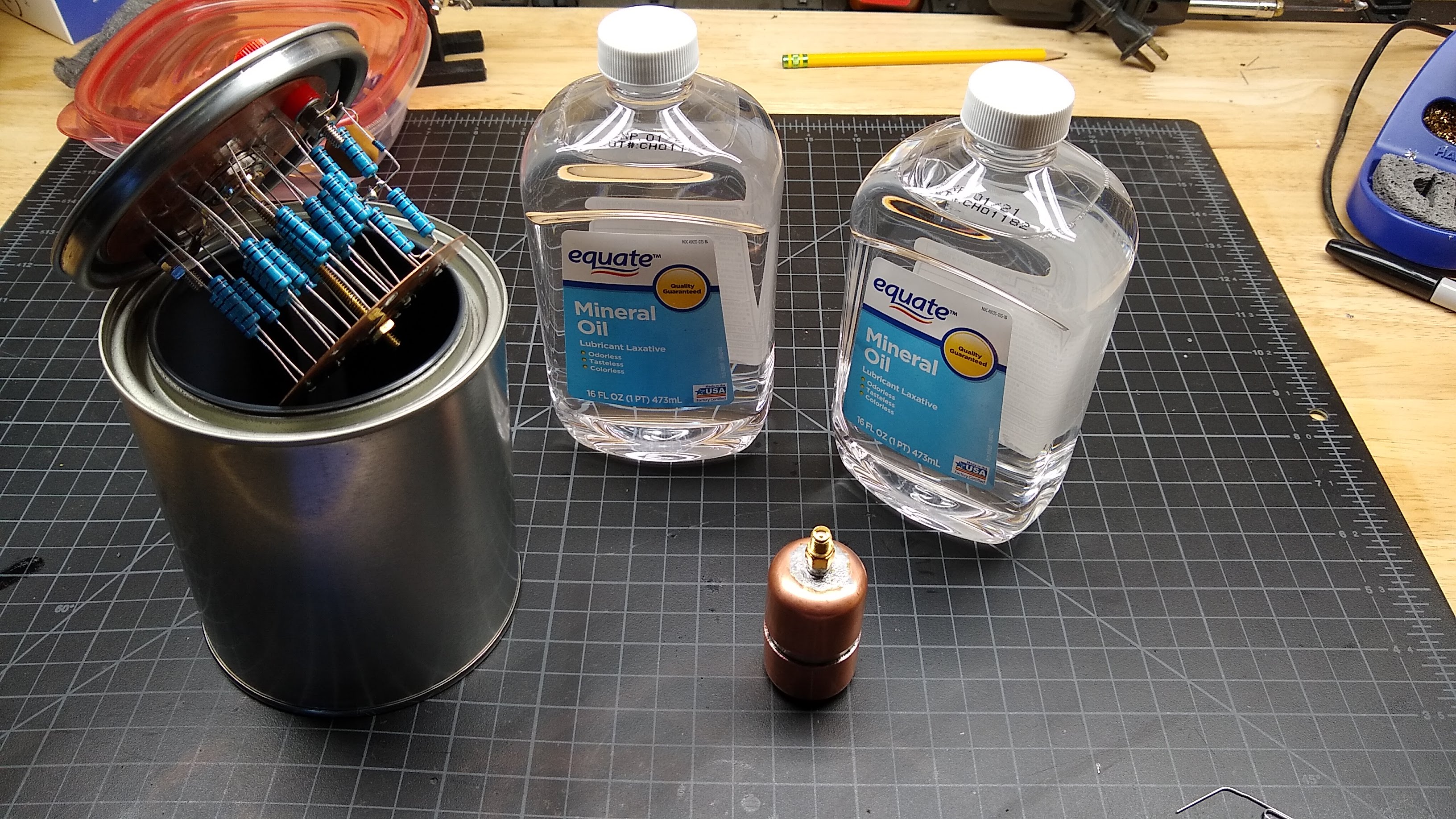
I decided to build a smaller version of the classic “Cantenna” dummy load. Not to be confused with the Pringles-can WiFi antennas we’ve seen plenty of before, a cantenna load is a big 50 Ω resistor in a paint can filled with dielectric oil for cooling. I chose to make mine in a quart (about a liter) paint can.
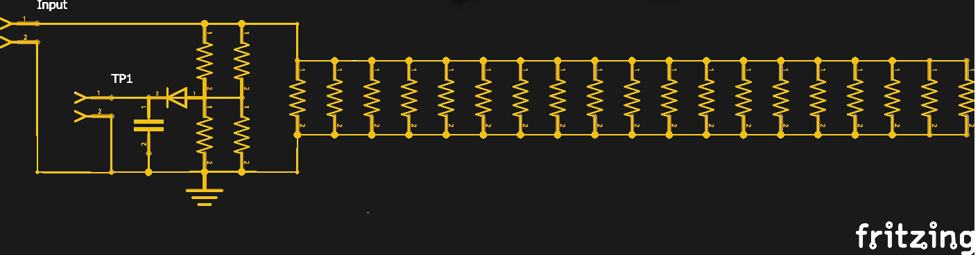
Resistor choice for Big Dummy was a little more difficult than sourcing a single 35 W thick-film SMT resistor was for L’il Dummy. Wirewound power resistors are easy to find, but as previously noted they’re entirely wrong for a dummy load, as their inductance would change the impedance of the load at higher frequencies. I finally managed to find 1000 Ω metal-film resistors in traditional axial lead packages. A pack of 30 only cost me a few bucks. The plan was to put twenty 1000 Ω resistors in parallel, resulting in a total impedance of 50 Ω. At two watts dissipation each, that should make the load capable of handling 40 W – close enough to my target 50 W.
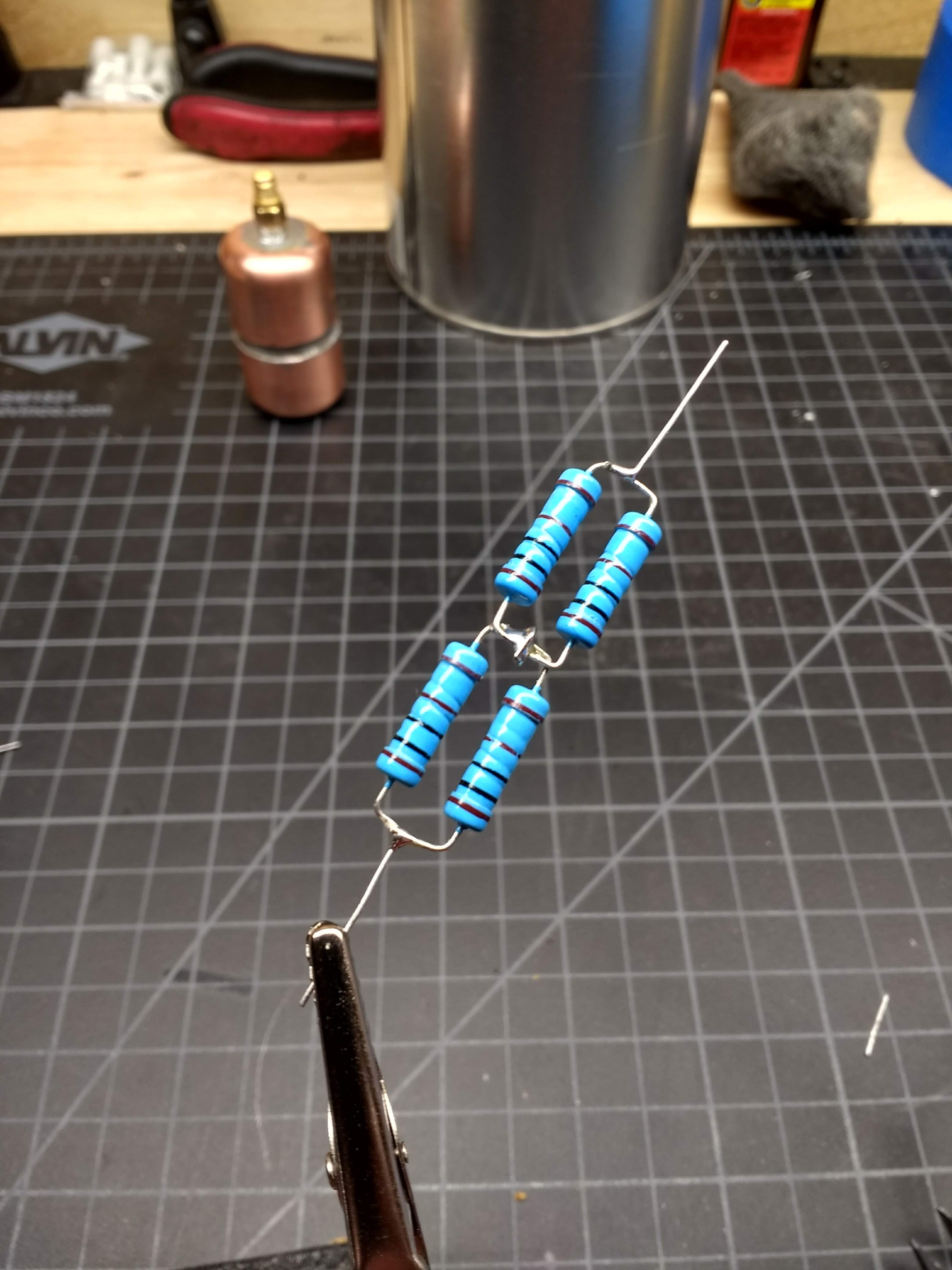
The tap for the test point was a modification on K7AGE’s design as well. He used a series-parallel network to build his dummy load, which gave him a natural tap point between two of the series resistors that acts as a voltage divider. I had to play a few tricks with the resistors I had to make up a network that does the same thing. I detail its construction in my Hackaday.io post, but the quick version is that four 1 kΩ resistors in a parallel-series arrangement did the trick, allowing me to install a 1N5711 Schottky diode and a small ceramic decoupling cap for the test point while maintaining an overall 50 Ω load.
The Build
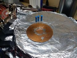
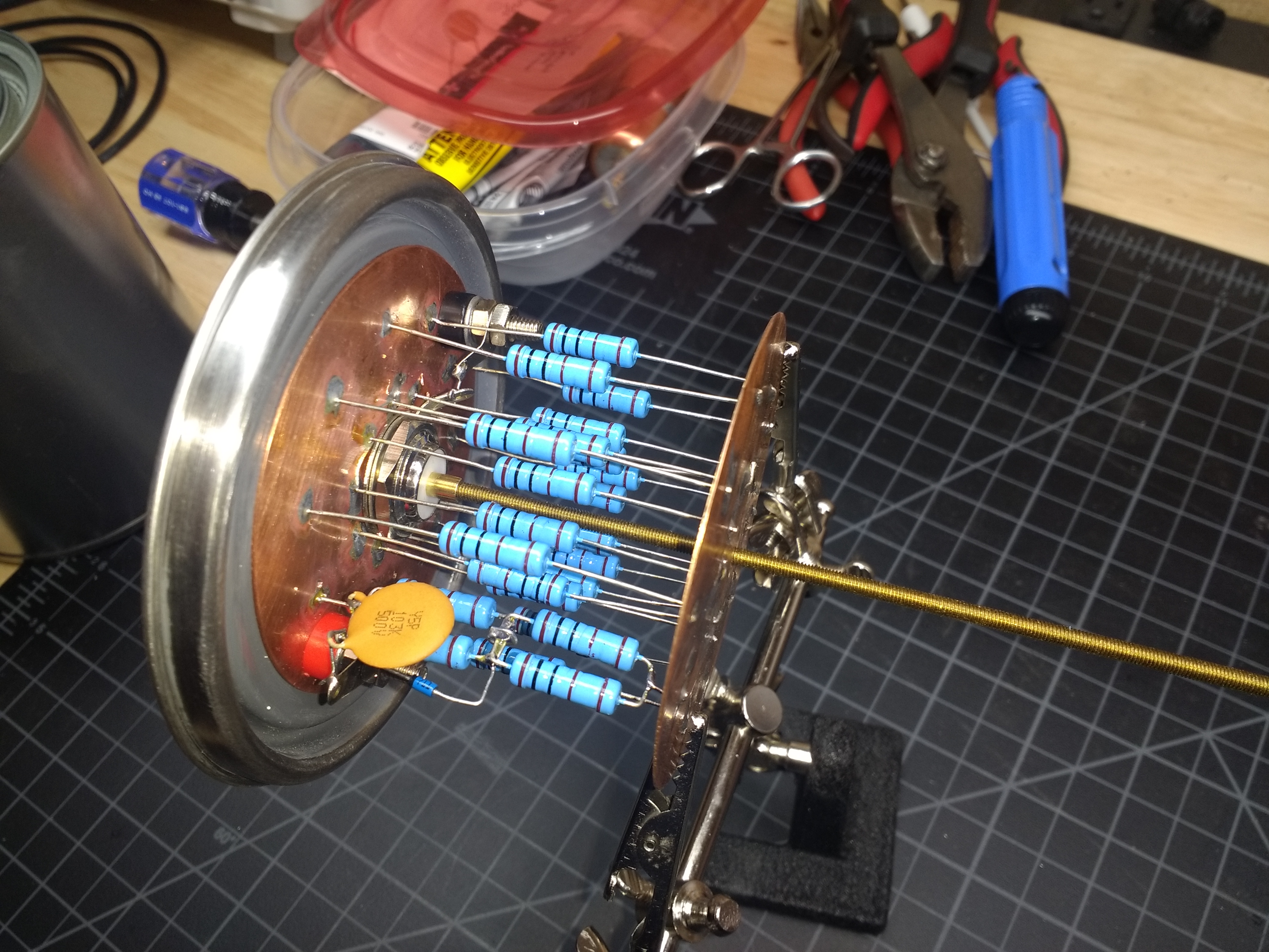
To keep stray inductance at bay, I decided to mount the resistors between two copper discs. This sounded like a way better idea than it turned out to be. I’ll leave the hijinks that resulted from that decision to the build log, but suffice it to say that trying to solder twenty resistors to a heavy copper plate is not as easy as you might think. I ended up using a cheap hot plate to heat the whole assembly evenly and soldering all the leads to one plate at the same time, then flipping the assembly over and doing it again.
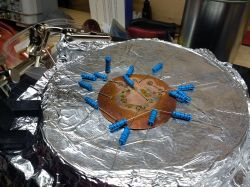
I finally figured out how to do it – the plates needed to be held together with threaded rod first, and I needed to use holes rather than dimples in the copper plates. That resulted in this beauty of overkill – I really dig circuit sculptures, and I wanted it to look good before taking a dunk.
Finishing Up
I chose plain mineral oil for my dielectric fluid. I was warned that oil-filled dummy loads always end up making a mess, but I decided to try it anyway. It took most of a liter of oil to fill the can, and I did get some initial leaking around the connectors penetrating the top of the can. I may have to add gaskets on some kind, but it’s fine for now if I just keep it upright.
I did the exact same test described in my last post to determine how flat the impedance of Big Dummy is across the range from 2.5 MHz to 20 MHz, the upper limit of my function generator. The data was almost identical to the readings from L’il Dummy, meaning this load is a flat 50 Ω across the ham HF bands. Unfortunately, I haven’t pulled my HF rig out of storage yet since moving across the country, so testing at full power and making some measurements using the test points will have to wait.
Next Time
I think I’ve really caught the homebrewing bug with these two builds, so I’m going to look for another cheap build to do for next time. I’m leaning toward characterizing the notoriously dirty output of the Baofeng and seeing if there’s a filter we can build to clean it up. If you have any ideas on that, please sound off below.


What’s this $50 nonsense? Have you any idea how much it costs to qualify for, and then remit yearly fees for an amateur licence in some countries? Dude, that’s a way rich man’s hobby! No wonder the very generous spectral allocations are as good as devoid of users.
Sorry for the folks who live in countries that extort high fees from amateurs, but here in the US licensing fees are nominal – maybe $15 to take the test, and that is often waived by the VE doing the testing, especially if it’s sponsored by a local ham club. And re-upping the license, which is good for 10 years, is also free. I even recently got a vanity call sign and that was free as well.
The whole point of this series is to show that ham radio is not just a rich man’s hobby. So far, I’ve shown that you can get licensed as a Technician and on the air for less than $50, and built two useful homebrew devices for about the same amount. Next we’re going to look at using an SDR dongle to replace a $1000 spectrum analyzer, in an attempt to clean up the admittedly dirty output of a $35 Baofeng dual-band HT transceiver. Later we’re going to show that getting on the air on the HF bands doesn’t necessarily mean spending thousands on a Yaesu or Kenwood rig, and that even building your own repeater can be done on the cheap. Sure, some of my projects will break the $50 budget, and there’s some assumption that you’ve already got a basic kit of tools and supplies, but by and large, a fifty dollar bill can buy a lot in this hobby, if you know what you’re doing.
And I completely disagree with the assertion that the bands are empty because it takes too much money to get on them. The HF bands are anything but lonely, and even when they’re quiet, it has far more to do with poor propagation conditions thanks to our sleepy sun than affordablity of the gear needed to get on the air.
Then there are the club fees, and ‘consultant’ services, without which you won’t get a either a requisite qualification or license. I reiterate…an inaccessible, rich, old boys’ hobby.
Like I said, sorry to hear that you live in an overly extortionate regulatory regime. But your experience doesn’t change the fact that many of us can enjoy the hobby on the cheap. My club cost $15 a year for dues, which I gladly pay just so they have a pot of money to keep the repeaters going.
‘THE USD50.00 HAM:’ a better title. No respect for the hobby, nor for it’s spoiled, exclusive and one-track-conversational adherents.
If I could tell you how an amateur ‘club’ ransacked the Wireless Hill Telecommunications Museum, carved-up important historical artefacts and distributed them amongst themselves, buried what they didn’t want, and substituted everything with worthless, unwanted, 60’s-era commercial junk…
They quite literally stole all the WWI and WWII equipment I was so fascinated by as a kid. Have you ever seen a mercury-vapour-filled glass valve the size of a Bongo van…an audio speaker reminiscent of the one Marty McFly hooked his guitar up to in ‘Back To The Future’? I think I might have been one of the last!
Yep that’s Germany for you. Been there and won’t be going back in this life time. Now I know why my great grandparents left and came to the U.S. in the early 1900’s. Seems things haven’t changed much in a 100 years when it comes to freedoms. Just a different title on the Gov. The fellow I was working for owns a piece of land over there and share crops it out, his family was fairly wealthy, made their money in Coal mining. He was always telling me about how no one could do much of anything over there outside of work and sit at home or the bars. Over crowded over priced, over regulated.
Soooo… What does it cost to get qualified for and licensed/renewed outside the U.S.? I’m genuinely curious.
In Germany you have to pay 80 € for the class E test, 110 € for the class A test (80 € if you passed the class E test before and want to upgrade to class A). Once you passed the test you have to pay another 70 € to get your license and callsign. Plus about 20 € of “Frequency protection fees” every year.
Class E operators are allowed access to 160m/80m/15m/10m at 100 W PEP, 2m/70cm at 75 W PEP and 3cm at 5 W PEP. Class A is generally permitted to use 750 W PEP, though some bands have other limits.
So to become a licensed ham in Germany you need to spend at least 150 € (~170 USD) right away, plus the Frequency protection fees, which are collected every couple of years. If you want to do 20m/40m (which to me seem to be the most important bands missing in class E) you’re out 180 € (~200 USD)
Being rich isn’t a requirement for amateur radio in Germany, but if you’re struggling to get by on your salary the fees are certainly a problem. And if you’re a minor, for example, and paying for the fees out of your pocket you might not be able to afford even a HT for some time because of these fees.
You should be glad to live in a country where you can get any license by studying and paying 15 bucks.
Yes… Yes we are.
You have perfectly explained why Americans are so unapologetically proud and patriotic. It’s not perfect here (yet), but we have good reasons to claim the title of Best Country in the World.
If you are looking for a low cost and part count transceiver, there isn’t much simpler than a Pixie style Morse code transceiver such as the one here: https://www.qsl.net/qrp/txr/micro80.htm
There are no build instructions on that site, but there are other variations that have instructions or have kits available. The key to the circuit’s simplicity is using the same transistors to both receive and transmit.
Chapter 1 of Experimental Methods in RF design has a few perfect projects for the beginning home brewer including full details for a simple transmitter like the QRP micro 80 and a companion receiver. I can’t recommend it enough. And chapter 1 is free from the ARRL site as I remember so that fits in your $50 too.
This makes me nostalgic for my Dads Heathkit HW101 and Cantenna builds from the mid 1980’s… I think this is a fun series of articles! Keep em coming… 73!
Ah, yes – the “Hot Water 101.” My elmer from when I originally got into ham radio as a lad had one in his shack. I can even remember the smell of it as it warmed up.
My first dummy load was a 47R carbon resistor that was a neat fit inside a coax reducer screwed into a “CB” antenna plug. Liberal amounts of heatsink compound was applied and the has run successfully for years at 10W or so for a few mins at a time. The plug gets pretty warm but is works and is a very good load on 2M.
And if you can get your hands on an old crystal locked HF rig, or VHF for that matter, an Arduino based VFO like the one I’m playing withe here…
http://sadarc.org/Projects/VK3ZYZ%20Arduino%20VFO.pdf is a good upgrade for about the price of a crystal.
Also, these HF rigs are cheap and make a good starting place…
http://www.hfsignals.com/index.php/ubitx/
Getting into Ham radio can be pretty cheap. Or expensive, depending on how you go about it. Modifying an old CB can get you on the air too, and there are lots of them just lying around.
Indeed, one of the stretch goals here is to modify an old SSB CB rig for use on the 10-meter band. I know it can be done, but I can’t find any step-by-step guides that would make it easy, and my RF-fu is still weak. As I recall, the “President” line of CBs from Cobra were the most likely victims for the 11-m to 10-m modification. Those still command a fairly high price on eBay, though.
If it is a smart PLL driven one you can likely replace the microcontroller one with your own. And program the PLL for the 10m band. Some older CBs have a simple digital circuit with diodes to configure the PLL, just change the diode matrix to configure new frequencies. You an also try to change the master clock frequency. You will not have a nice channel spacing, but the whole band will shift up.
Even older ones use one or two crystals per channel, replace the crystals with ones made for the frequencies you want.
In all cases you may need to tune the RF circuit a little bit to get optimal performance. Likely streching a few coils will do.
Actually, 23ch CB radios were bought up by the 10’s and 100’s when stores could no longer legally sell them (When 40ch began). I was in retail back then and $300 SSB radios (pre-40) were discounted to less than $50. Eventually entire inventories of new PCB’s found their way to the market for $10-$15, and Hams converted these to 10m fairly easily back then. There were quite a few articles in various magazines on converting them, so hopefully they can still be found archived, and I believe you would find it much easier to re-work a non-PLL CB to 10m vs. one w/PLL.
In specific, the Hy-Gain model 674 am/ssb mobile (kinda large for a mobile now) was modified to 10m quite often. It had several versions, but one in particular had a VFO jack in the back which mated to the matching 675 VFO. While many pairs of these made it to 10m, many were re-tuned using the VFO for easy coverage between ch. 23 and 27.555. While the VFO was for receive-only, there was supposed to be an easy way to make it work on transmit as well.
TAB books put out a series of repair books featuring many popular radios (like CB SAMS) and Vol.1 covers both the 674 radio and 675 vfo.
I have a “pair” of these lurking in storage and now that I’ve typed this, maybe that will be enough motivations for me to tinker with it. Keep up the great articles!
FLEX SEAL
Dan, buddy….what are you doing? My project list is already longer than my arm. Good job on these articles, they’re compelling.
Who needs no stinkin oil? https://www.youtube.com/watch?v=u0qfSMWyjaw&fbclid=IwAR1YGDsyexslj-yBTyymB78KOryy_SOk-Hb6UmYg5ZSjzkr64XSrCRw5NhA
found these to be a great starter kit and its a 20W dummy load that appears to work well on HFVHF,UHF https://shop.rocketcity3d.com/20-Watt-QRP-Dummy-Load-Kit-p148240036