Reading the temperature of your environment is pretty easy right? A quick search suggests the utterly ubiquitous DHT11, which speaks a well documented protocol and has libraries for every conceivable microcontroller and platform. Plug that into your Arduino and boom, temperature (and humidity!) readings. But the simple solution doesn’t hit every need, sometimes things need to get more esoteric.
For years we’ve been watching [Edward]’s heroic efforts to build accessible underwater sensing hardware. When we last heard from him he was working on improving the accuracy of his Arduino’s measurements of the humble NTC thermistor. Now the goal is the same but he has an even more surprising plan, throw the ADC out entirely and sample an analog thermistor using digital IO. It’s actually a pretty simple trick based on an intuitive observation, that microcontrollers are better at measuring time than voltage.
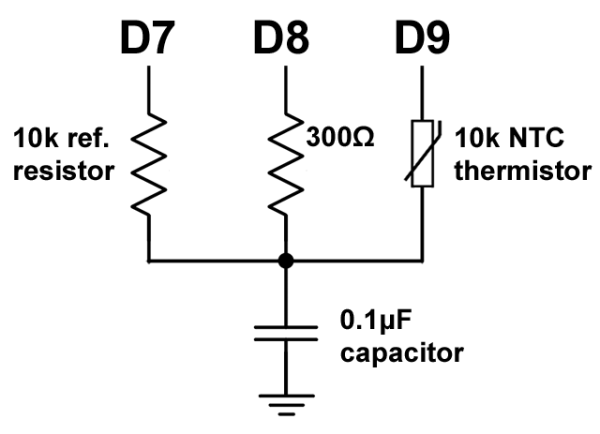
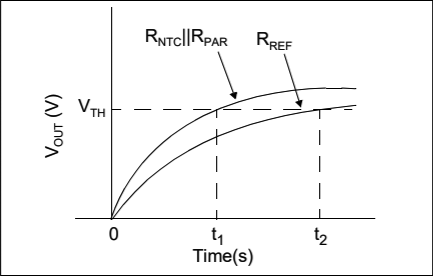
The circuit has a minimum of four components: a reference resistor, the thermistor, and a small capacitor with discharge resistor. To sense you configure a timer to count, and an edge interrupt to capture the value in the timer when its input toggles. One sensing cycle consists of discharging the cap through the discharge resistor, enabling the timer and interrupt, then charging it through the value to measure. The value captured from the timer will be correlated to how long it took the cap to charge above the logic-high threshold when the interrupt triggers. By comparing the time to charge through the reference against the time to charge through the thermistor you can calculate their relative resistance. And by performing a few calibration cycles at different temperatures ([Edward] suggests at least 10 degrees apart) you can anchor the measurement system to real temperature.
For all the gory details, including tips for how to save every last joule of energy, check out [Edward]’s post and the Microchip appnote AN685 he references. Besides this series [Edward]’s Cave Pearl Project has already yielded an impressive number of Hackday posts. For more great hardware writeups check out a general hardware build for a single sensing node, or the “temperature sensor” [Edward] made with no external parts at all!


1st.
Neat tho
But… but… hysteresis, imprecisions in Vlow(max), Vhigh(min)… are not important? PSRR? VDD drop due to battery discharge? Isn’t this method also tied to the CPU’s measuring voltage capabilities? Since he’s using a capacitor’s charge/discharge ramp, the inputs and outputs will no longer behave as digital. For instance, one LED connected to another output will affect the voltage used as a reference for the capacitor.
Your concerns are real. Most parts today are CMOS where the “C” stands for complementary. When a CMOS output switches, there is a transition where the both N and P channel devices are on, which can generate a lot of self-induced noise both in the part and back into the system supply. That’s why GOOD bypassing is so important. Some micros let you turn off either the N or P channel transistor, which can help with noise if it helps with the target design. Also, the switching thresholds can change significantly with temperature, which is seldom if ever characterized in the data sheets, so there is no reliable way to “design for” those variations. Sometimes even having extensive temperature calibration tables inside the equipment to adjust for MEASURED changes during design (preferred) or factory (expensive and slow) calibration — of course, that depends on being able to measure temperature reliably (not necessarily accurately per se, but consistently within a given framework, since the external factory calibration equipment ensures the temperature accuracy of the testing).
I worked for a company that made ground-based avionics for the FAA. Equipment temperature requirements were that equipment had to work “within spec” over the temperature ranged of -40 (northern Alaska) to +75 (Death Valley) degC. Because of the low temp, we originally could ONLY use (very expensive) Mil parts to meet temperature requirements. Once the industry decided they no longer wanted to do exotic Mil part testing, they offered more and more industrial temp parts, which we eventually switched to in spite of the FAA’s protests (they had forgotten that the purpose of using Mil parts was temperature range, not reliability, which actually was often less due to the high-stress of Mil testing). All of our designs were tested extensively in temperature chambers both small (for boards) and large (for entire systems), as required by contract. Temperature testing has a way to quickly shake down inadequate designs. And the later the catch a problem, the more expensive a redesign becomes. Too many Mil parts were sole-sourced, crippling the ability to do a simple part-replacement redesign.
Also, a pet peeve of mine is the common practice of using resolution, precision, and accuracy interchangeably, although the latter two are closely related. These are not the same, and it’s important to know their distinctions especially in big contracts and especially safety critical applications (e.g. avionics). Just because you can get more resolution by doing “tricks”, that doesn’t guarantee that accuracy improves also.
How does the time constant of an RC circuit vary with voltage? The real question, though, is, is the circuit good enough for the purpose? I’m betting that for the home gamer, the answer is, “yes,” especially if the time constant is large enough,
Voltage does not appear in the expression for the time constant.
Exactly my point.
Capacitors vary their capacitance with voltage – especially ceramic capacitors. This can be as high as 70-80% of the nominal value over the rated voltage range.
There’s also dielectric absorption, which causes a time-varying capacitance change.
He has re-invented the Wilkinson ADC that was first done in the 1950s. It has the advantage of very good differential linearity but is very slow. Generally, however, for e Wilkinson-type ADC one measures the discharge time of the capacitor rather than the charge time, thus avoiding all the problems of the stability of the voltage supply. If desired, one can discharge two calibrated capacitors, one with a known resistance and one with the variable resistance.
Can you calibrate out the self heating of the thermistor? Perhaps normal capacitor charge curves can help. His other posts suggest they are very sensitive to minor heat loads. How does he know he’s got 0v on the cap each time he starts the cycle? Perhaps rotate which side is measured first each time?
Doesn’t this also require a low error clock in the timescales concerned, if we are comparing two times? I may recall wrongly but he’s using external RTCs elsewhere in the cave pearl. A possible source of timing improvement
Similar to the way used to read joysticks with the IBM PC game-port.
And many many other brands, types and models of computers of the 80’s.
But despite the fact that the “little trick” mentioned in this article is nothing new. It’s always good to dig up the tricks of the past, simply because we seem to forget the easy things because we are spoiled with high-end circuitry for the costs of next to nothing. Playing with these concepts from the past it allows for a better understanding of what we are doing or could be doing in our current or next design. Sometimes, we don’t need high-end but do need to jump through hoops to make a project work better or more versatile. Sometimes even when the design has reached a stable state and hardware cannot be altered other than simple component values. Then it’s good to have a bafg of tricks to dive into…
A long time ago I had a project that had no spare IO, but had 2 different kind of uses. It therefore required two different kind of firmware, BUT it had to have the same firmware in both. Therefore it required both version of the firmware to be combined and automatically detect on which hardware it ran, so it could choose the correct code from there on. There was no spare IO. I used the microcontroller’s ADC that was connected to a series of resistors and buttons (the buttons were placed across a set of resistors forming a voltage divider, so pressing a button creates a different voltage), it had a small capacitor to reduce the input noise. So I decided to have a value of 100nF on one PCB and 220nF on the other. This could be detected in a sort of similar (actually simpler since accuracy wasn’t a big issue) way as here, I disabled the ADC, used the IO-pin as regular IO charged it by making the IO-high (1) then switched the IO-pin to input and measured how long it took to fall to 0. After that the microcontroller switched the IO-pin to ADC mode to measure the buttons normally. This trick did not affect normal functionality and worked like a charm.
I have contemplated, but never built, a variation on this theme using a comparator.
The idea is to output a PWM duty cycle to a low-pass filter and pass that analogue voltage to one side of the comparator, with the comparator output taken to a digital input.
If the comparator trips you reduce the duty cycle, if it isn’t then you increase it. So the PWM duty cycle tracks the input voltage and can be used as a proxy for it.
I can’t decide whether this tracking ADC gives better or worse bandwidth than the one-shot version.
This idea was thought up as a way to read analogue voltages with a parallel port and software PWM, but it ought to work better with hardware PWM from a microprocessor.
It is simple BUT PWM with low pass filtering is still a very noisy source. Garbage in one side of comparator = garbage out. You are much better off with sigma delta ADC with your comparator or just RC charge/discharge timing as they have much higher resolution.
The noisy reference voltage might actually be an advantage, giving more comparator transitions to work with.
There are multiple problems with PWM, so that’s why it is not used in any real ADC.
– trade off with PWM resolution vs frequency.
– hard to filter without resorting to high time constant i.e. very long settling time
Between these two, you can really get any high res without high order of RC filter, long conversion time.
You should at least try spice or use a scope to look at the filtered PWM. You only want your noise to be a small fraction of your signal just enough to dither or it would just drown the SNR. Just a straight up conversion would take a long while and you want to get multiple samples just to get clean enough reading. You could have a lot better S/N, resolution and conversion time with those other methods.
All good points, though we are talking about measuring environmental temperature here so a long time constant is likely to be bearable.
Bit-banging an SPI dedicated ADC is probably at least as useful, in practice.
IIRC the Apple II used a similar scheme to read the joystick.
That sounds sort-of like a delta-sigma (sometimes referred to as sigma-delta instead, I forget which is correct) ADC. Not quite the same concept, but similar.
how accurate did he get it across PVT?
You do want to be sure your chosen microcontroller digital GPIO pin doesn’t behave badly when the input line sits at an intermediate voltage (above the maximum for 0 and below the minimum for 1) as some CMOS buffers will. Most modern uCs can handle this though it’s worth looking at the datasheet since the mode of failure when a pin is vulnerable is over-spec power dissipation at the output side of the input buffer as both the high and low drivers can be partially on. Looking for a Schmidt triggered input is a 0th order way to see if the designer considered in-between inputs.
Many micros put analog and digital inputs on the same pin but have a mix or switch that disconnects the digital input and connects it to an internal pull-down instead if you enable the analog function on that pin (e.g. ANSELx on PIC32 parts).
this is a good point. i don’t know about atmel parts but most PICs have a few schmitt triggered inputs in their GPIO pins. always a good idea to actually look up the diagram for the pin you plan on using, since there is such a wide variety between the different GPIOs on some of these devices.
it seems to me as though if he has all the components (including the microcontroller) at the same temperature, then it doesn’t need accuracy, only repeatability. the fact that the time base, logic gates, capacitor, and reference resistor all change with temperature doesn’t matter so long as it repeats the same behavior it showed when it was calibrated.
The 558 (basically a Quad 555 timer) was popular with PC joysticks. Four channels were necessary to obtain X and Y for two joysticks. Needless to say it was still an RC time constant driving the 555’s and then to the PC rather than driving the PC directly.
The 555 approach may be “cleaner” to the PC and require less software overhead (i.e. just measure the pulse width), however the reference resistor on the direct PC approach might provide a more accurate result since it can be used to provide a ratio-metric value that negates/minimizes variations due to temperature on the base capacitor and resistor being measured.
“Plug that into your Arduino and boom, temperature (and humidity!) readings. But the simple solution doesn’t hit every need”
To be honest the DHT11 doesn’t really hit many needs at all. The accuracy is horrible :/ It only does whole degrees and is usually a few off. Bwah.
The DHT22/AM2304 is a little bit better but the more modern modules are way better.
By the way for temperature I really recommend the Dallas DS18B20. They are excellent and the one-wire bus is handy (if a bit slow) if you have a bunch of them.
For temp/hum I don’t really know any really good ones first-hand. But I’ve heard good things about the SHTxx series from Sensirion.
You can also measure temperature by timing the reverse-bias charge decay on ANY type of diode. This makes high resolution readings possible without the op-amp you often see used with diode based methods that measure the change in forward voltage. So we are currently trying to decide between thermistors vs. diodes for ambient temperature sensing. As a bonus, the two devices are close enough that I can even use the same Steinhart & Hart calculations over a range of about 30C:
https://thecavepearlproject.org/2019/11/04/single-diode-temperature-sensor-with-arduino-icu-via-reverse-bias-leakage/
With the sensors being so cheap, and the method being workable with ANY resistive sensor, we include both NTC & LDR sensors on all the classroom loggers. Then the students can do calibration labs against an I2C temperature sensors. To free up an extra digital pin on those builds we use the internal pullup resistor on D8 as the reference resistor instead of a 10k on D6. This will undoubtedly have more drift due to aging, but the S&H constants absorb thermal variation on that internal pull pretty well.
https://thecavepearlproject.org/2023/12/01/the-e360-a-classroom-data-logger-for-science/