Even a relatively low-end desktop 3D printer will have no problems running off custom enclosures or parts for your latest project, and for many, that’s more than worth the cost of admission. But if you’re willing to put in the time and effort to become proficient with necessary CAD tools, even a basic 3D printer is capable of producing complex gadgets and mechanisms which would be extremely time consuming or difficult to produce with traditional manufacturing techniques.
Once you find yourself at this stage of your 3D printing career, there’s something of a fork in the road. The most common path is to design parts which are printed and then assembled with glue or standard fasteners. This is certainly the easiest way forward, and lets you use printed parts in a way that’s very familiar. It can also be advantageous if you’re looking to meld your own printed parts with existing hardware.
The other option is to fully embrace the unique capabilities of 3D printing. Forget about nuts and bolts, and instead design assemblies which snap-fit together. Start using more organic shapes and curves. Understand that objects are no longer limited to simple solids, and can have their own complex internal geometries. Does a hinge really need to be two separate pieces linked with a pin, or could you achieve the desired action by capturing one printed part inside of another?
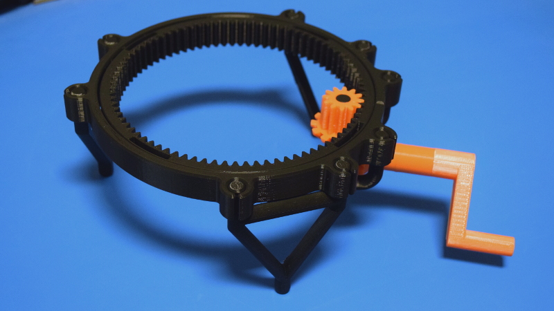
If you’re willing to take this path less traveled, you may one day find yourself creating designs such as this fully 3D printed turntable by Brian Brocken. Intended for photographing or 3D scanning small objects without breaking the bank, the design doesn’t use ball bearings, screws, or even glue. Every single component is printed and fits together with either friction or integrated locking features. This is a functional device that can be printed and put to use anywhere, at any time. You could print one of these on the International Space Station and not have to wait on an order from McMaster-Carr to finish it.
With such a clever design, I couldn’t help but take a closer look at how it works, how it prints, and perhaps even some ways it could be adapted or refined going forward.
Avoiding Disappointment
With cranks, gears, and a massive interlocking bearing assembly, you certainly couldn’t be blamed for thinking this would be a challenging print. But Brian has managed to keep the complexity of his turntable down, at least in part, by having a relatively low part count. The fact that the turntable bearing itself prints in one piece goes a long way towards this goal.
Of course, you’ll need to have a printer that’s relatively well tuned, but really that should go without saying any time you’re looking to print something more complex than a simple bracket. The trick with any print-in-place design (which is FDM parlance for a single print that incorporates moving elements) is making sure the parts don’t fuse together. So one of the major things to look out for is over-extrusion, which tends to make things thicker than they should be.
That being said, Brian has made the tolerances wide enough that even entry-level printers shouldn’t have a problem. In fact, the clearances might be a bit too forgiving. While it’s not a critical issue, I found there’s a bit more play in the rotation than seems necessary because of how much smaller the inner ring is. Beyond that, the fit on all the other components is spot on, and everything holds together with friction alone.
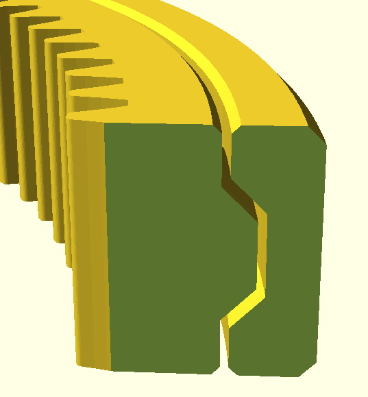
If there’s any major pitfall with the design, it’s that you’ll need essentially perfect first-layer adhesion when printing the bearing since a raft or brim would almost certainly cause the parts to fuse early on. The good news is that the circular outer shape is not particularly prone to curling or otherwise lifting off the bed. Unfortunately, all those teeth on the inner ring could be a stumbling block if your printer doesn’t get the initial bead of filament down cleanly.
Printing and Assembly
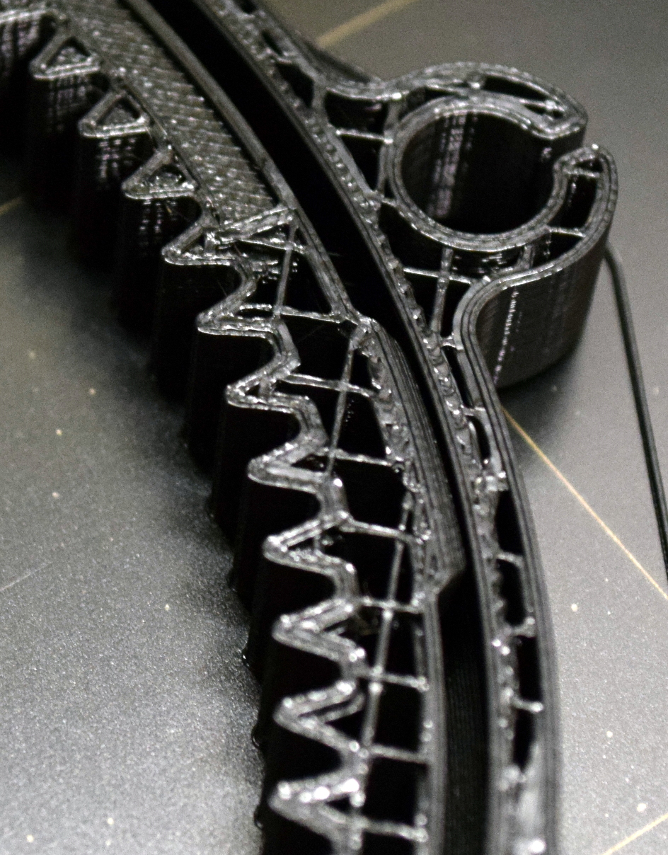
As mentioned previously, the major hurdle in this project is getting the bearing printed. Not only is this the hardest part to produce, but also the most time consuming. Despite all that, it’s where I would recommend starting; because if you can’t get the bearing printed out and spinning freely, then there’s no point in bothering with the rest of the parts. On my Prusa i3 MK3, it took a little over six hours to print the bearing at a layer height of 0.2 mm.
Once the bearing is out of the way, the rest of the print is really pretty smooth sailing. With as simple as the legs are I ran all three of those off at once, for a total print time of around two hours. The handle and gears each take around an hour to print, and all went off without any problems. One minor annoyance was that many of the parts are not properly oriented in relation to the bed when loaded, so you need to manually rotate them before slicing. It’s a small thing, but hopefully Brian can address it in a later update to the STLs as it does make it a bit harder for less experienced users to get good results.
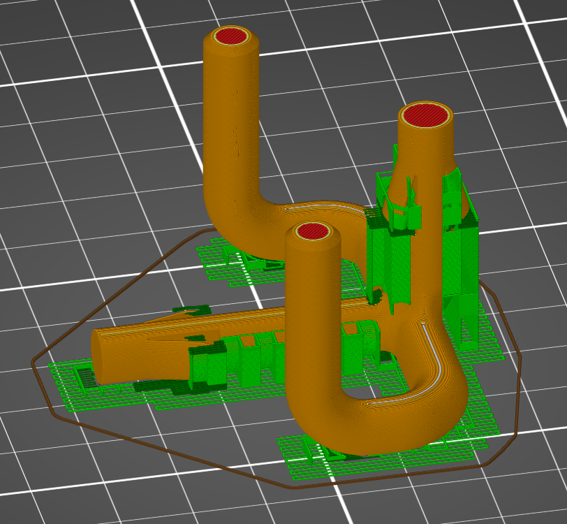
While not as difficult as the bearing, you’ll likely want to slow things down a bit when you get to the “plumbing”, which is what Brian calls the piece that holds the gears. This part is not only a bit spindly, but features integrated locking mechanisms which need some special care. I dropped the layer height down to 0.1 mm and enabled automatic support generation. I probably could have improved on things a bit using the new custom support options in PrusaSlicer, but the default settings did a decent enough job and the cleanup wasn’t too bad.
Once all the parts have been printed, a task that should take you around 14 hours or so, it’s time to assemble your little pile of plastic bits into a working turntable. The process is fairly self explanatory, but if you’re unsure of anything, Brian has provided a short video that does an excellent job of visually explaining how everything is supposed to fit together.
A Personal Divergence
On the whole, I think Brian has done an excellent job with this design and it serves as a perfect example of how one can play to the strengths of desktop 3D printing. Still, there was one element of the design that I thought might benefit from a different approach. Originally, the turntable was to be topped with a removable plate that would have a piece of paper taped to it. Printing this solid plate would have taken over three hours given the large surface area involved. That seemed unnecessary given the fact it would be covered with paper anyway.
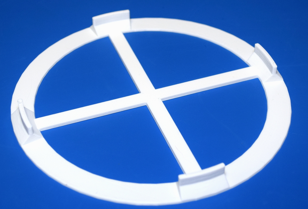
For my own use, I made a modification of the original top plate STL that minimizes the surface area in contact with the printer’s bed. By making the outer diameter smaller and replacing the solid center with a simple cross, I was able to reduce the print time for this piece to under an hour. Brian says he’s also looking into alternate surface geometries that could be used to reduce print time and material for this particular piece.
Scientific Spinning
Since printing this turntable, a considerable chunk of my free time has been devoting to taking videos and pictures of spinning objects. There’s something extremely satisfying about using this little gadget, knowing that you produced every component of it in-house. Many designs presented as “fully printable” often still require a few screws, bearings, or other mechanical components to complete, but not this one.
While a fun toy to play with in its current form, I’ve found myself wondering about a possible future enhancement to the design which would allow you to remove the crank assembly and replace it with a small stepper motor. This would allow for smoother rotation in videos, and put you well on the way towards an automated photogrammetry rig. I’ve mentioned the idea to Brian, so who knows, perhaps in the future this little turntable will learn some new tricks.


I’m curious how other people handle tolerances when pieces are meant to have a decently tight fit. I’ve found that generally my prints are slightly (but not uniformly) bigger than spec. I know I could in theory solve this by using more aggressive calibration techniques, but what I do instead is this hack. I define a value I pronounce “edge extra” and spell “ee=0.2” at the top of my scad files (I love openscad so much). And for every tab or slot that seems critical, I add or subtract ee on each wall of it. For example, a typical tab would be -ee on both sides, for a total loss of -ee*2. A slot would be the opposite, +ee*2. A hole with cylinder() gets r=..+ee. A peg would be r=..-ee. And so on. I use ee=0.2 if I feel like it’s important that things be tight, or I use ee=0.3 or ee=0.4 if I just want to make sure I don’t have to do any trimming.
My feeling is that even if your printer is very carefully calibrated to not over-extrude and so on, you will still have some irregularity that will force this, or you can make up for it with a lot of extra work with the x-acto.
How do you all deal with this?
I do the same in my OpenSCAD designs, makes it easy to fiddle with the tolerances. For more complex shaped parts, I will sometimes scale up the one side to something like 1.01, then difference() that from whatever the final print needs to fit into.
I’ve been printing a number of captive pivots like this lately. It’s really trial-and-error with the scale parameter (for me) because how much the part absolutely expands depends on how big it is. In principle, you could do some math to figure this out…
Anyway, to get a really tight, but moveable captive hinge/pivot, I’ve been reducing the extra scale until it just starts to bind. Then I take it down to the basement, clamp one half in a vice, and gently, gently tap the other part until it comes free. With PLA — other plastics will probably behave differently.
Yes, I’ve also sheared a couple in the process, but it ends up with a part that’s just about as tight as it could be, given my machine/tolerance/filament.
I’ve found and done similar things myself, although in FreeCAD.
However I’ve found my printer (modified Anet A6, but stock frame) does the outside pretty much right but the inside well under-size, so I’ve only worried about there…
I’ve been experimenting with the “post stretch” script packaged with cura. It adjusts the gcode to compensate for undersized inner features. The benefit of fixing it during slicing is better layer adhesion vs. oversizing holes in CAD.
The script is a bit rough around the edges, but I’ve been trying to fix it up as I find bugs. I just did a print where a bolt actually fit into its clearance fit hole without reaming it out!
I do the same in my OpenSCAD scripts. But instead of making up my own name, I use the engineering convention name for this sort of thing so I label it TOLERANCE. ie. TOLERANCE=0.2; //mm
see https://en.wikipedia.org/wiki/Engineering_tolerance
Yeah, except scroll down on that same wikipedia page: I think you mean “fit”. Tolerance is how tightly the parts are machined to spec, while fit is the extra slop that you allow depending on the tolerance and how tight you want parts to, well, fit.
I always call the parameter “wiggle”. But sometimes it’s worth specifying interior and exterior wiggle, etc…
I’ve not encountered a 3D printer that is so accurate that can print to a fit. In machining metals there are various grades of fit (not detailed in that link), and these are defined by ANSI and ISO. Slip fit, running fit, slide fit, shrink fit are the main ones. If your have a printer able to dial these in with good repeatability, you’d be able to call it fit but a plus/minus tolerance is the more suitable term.
If you’re using Cura as your slicer, it has an option called “horizontal expansion” that (given a positive or negative value) will do this automatically – it basically means “How much bigger is your print than it should be?” and I have mine currently set to -0.08mm, which makes a remarkable difference.
This one shows how you can do automated compensation in “Slic3r”:
https://www.thingiverse.com/thing:2221310
(down in “notes” and in the pictures is the description)
As you suggested, I hyper calibrate my printer. However, consideration must be given for shrinkage and expansion depending on each material source. This is the primary reason I stick to 2 filament sources and 2 resin sources. I tend to print a calibration cube with each, and i label the bottle or spool with +/-% to compensate the model with.
Here’s a tip on how to make slots and holes in FDM prints which will accept components with sharp corners, without needing work with a knife or file.
For example, to make a square hole for a square shaft. Make the square hole then place a small cylinder at each corner, with the cylinder’s centers on the square hole’s corners. Subtract the cylinders so the square hole now has an ‘ear’ at each corner.
If you’re making a thin slot, like for a thin piece of metal to fit into, use a single cylinder at each end of the slot. You want the cylinders’ diameter larger than the thickness of the slot, with the corners of the slot tangent to the side of the cylinder. When the cylinders are cut from the model the tab should slide in with no sideways wobble. If the tab is especially narrow, the cylinders can be made as ovals so there’s more support on the broad faces of the slot.
When printed, most of the cylindrical cuts will be filled in due to the inability of FDM printing to make sharp inside or outside corners.
This is an adaptation of a way to fit square shafts into machined metal parts when you don’t have a broach or other tool for plunge cutting sharp inside corners. Drill holes at the corners, positioned so the corners of the shaft or tab will have somewhere to poke out into, then mill the rest of the hole with conventional end mills.
I used this technique to 3D model and print a complex bracket for the yarn break sensor on some Brother electronic knitting machines. Brother never offered the bracket as a separate repair part, it only came with the complete ‘tower’ rod with some other parts attached. The bracket snaps onto a thin metal tab, has a round hole for a metal rod and a square hole for the yarn break sensor to snap into. The three holes go three different directions so I chose to orient the part with the tab hole straight up due to that being the one that breaks.
I received a shaft with broken bracket at noon-ish in the mail. Measured it with digital calipers and had it modeled, printed and everything mailed back the same day, before 4:30 when the local post office closes. That’s including a test print of part of the bracket to check the fit of the section that snapped onto the metal mounting tab. Perfect first try.
I found something different, actually. My printer is an i3 rework clone, with leadscrews and a couple other modifications, and it does spot-on size in the outside (down to 0.04mm, which is unbelievable to me). Inside features shrink around 0.4mm (as long as they are in the XY plane, otherwise they come out with the right size). If I want press-fit, then I make the holes 0.4mm larger; if i want some slip, 0.45 is fine.
Changing horizontal expansion is bad because it will also change the external features, so it’s not the same as knowing your own printer and designing based on that.
If I had a printer , how I would deal with it, and I am no engineer, is print out the part with a looser tolerance for a pressfit bronze or teflon bushing . If I was feeling really rich, id use some RC car bearings and pressfit them inside. Dunno but perhaps I am over simplifying it
FYI good airsoft BBs are surprisingly well made and can be used for printed plastic bearings…as for the tilerances – print, measure (!when cold!), adjust, print again.
Most of the offset will be caused by thermal expansion (well, shrinking) of the plastic rather then imperfections in the printer itself, so it will vary not only with the ambient temperature, but also with the shape, material and heat settings :P
That’s certainly the conventional way to do this, and would quite likely perform better – this feels like a design exercise in making complex mechanical assemblies which are 100% printed and don’t rely on any outside parts or fasteners. A useful tool to have in your metaphorical toolbox even if you don’t use it every day.
Adapt the design to fit a strip cut from the edge of one of those thin HDPE kitchen cutting mats between the inner and outer rings around the top. The top plate would keep it in place. Get the dimensions right and the strip should take up all the slack so there’s no wobble. Could do the same on the bottom, with the addition of a part to snap in to hold the strip.
No need for the X in the middle of the top plate if you rest a board or sheet of plastic on a ring shaped top plate. Or modify the inner ring’s top face to project a little above the outer ring so something can rest on it without dragging on the outer ring.
Do you have STL’s of the modified top plate available?
The main problem with holes in a design is that the STL model of the hole is based on a certain number of line segments that have the endpoints on the circle, instead of the midpoint, putting the lines inside the circle instead of outside. That works fine for pegs that have to fit in a hole of a certain absolute size, but holes end up too small. Fortunately, a little bit of trig will give you the radius of a circle of the proper size: new_radius = old_radius / cos(360/(num_segments*2)). For example, if you want to have a 10mm hole with 6 segments, you’ll need to define an 11.55mm hole. Does that make sense?
This is great info. Replying as a bookmark.
There’s a little notch on the surface of the outer ring which I thought might be a cool mechanical feature: to allow for the tolerance between the inner and outer rings, I wondered if there was a cutout part providing space for the outer ring to be squeezed together, which would tighten up the conical bearing surfaces like tightening the gibs on a machine tool’s slideway. Ideally a nut/bolt would clamp this but if you want to continue the 100% printed thing, perhaps use multiple pairs of peg holes at slightly different spacing for the bevel gear assembly to bridge.