There’s something seriously wrong with the Arduino walkie-talkie that [GreatScott!] built.
The idea is simple: build a wireless intercom so a group of motor scooter riders can talk in real-time. Yes, such products exist commercially, but that’s no fun at all. With a little ingenuity and a well-stocked parts bin, such a device should be easy to build on the cheap, right?
Apparently not. [GreatScott!] went with an Arduino-based design, partly due to familiarity with the microcontroller but also because it made the RF part of the project seemingly easier due to cheap and easily available nRF24 2.4 GHz audio streaming modules. Everything seems straightforward enough on the breadboard – an op-amp to boost the signal from the condenser mic, a somewhat low but presumably usable 16 kHz sampling rate for the ADC. The radio modules linked up, but the audio quality was heavily distorted.
[GreatScott!] assumed that the rat’s nest of jumpers on the breadboard was to blame, so he jumped right to a PCB build. It’s a logical step, but it seems like it might be where he went wrong, because the PCB version was even worse. We’d perhaps have isolated the issue with the breadboard circuit first; did the distortion come from the audio stage? Or perhaps did the digitization inject some distortion? Or could the distortion be coming from the RF stage? We’d want to answer a few questions like that before jumping to a final design.
We love that [GreatScott!] has no issue with posting his failures – we’ve covered his suboptimal CPU handwarmer, and his 3D-printed BLDC motor stator was a flop too. It’s always nice to post mortem these things to avoid a similar fate.


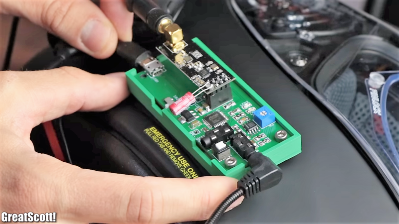
Nice case though.
https://youtu.be/YJ25eQRbhaQ And here is how to fix it
Andreas Spiess is great! I found him on here and have built some of the Demos d1 mini chore reminder things. He has a Patreon if anyone wants to sponsor him.
TL;DR just a single resistor change, but watch it anyway
To fail, is a learning process. I also have a lot of failed projects. But never give up! never surrender! :)
Sounds familiar https://hackaday.com/2018/07/23/fail-of-the-week-esp-walkie-not-so-talkie/
The guy with the swiss accent fixed it!
https://www.youtube.com/watch?v=YJ25eQRbhaQ
TL:DW; He was overdriving the input stage, distorting the op-amp. Solution was knocking the input signal down.
Andreas works through debugging the project in great / stepwise detail, and I really like his approach of sitting down and first thinking, OK, what blocks can I split this up into, and which should I approach first. Very engineery. :)
Myself, I would have just stuck a ‘scope probe everywhere along the signal chain until I found something wonky. And only once that failed, take the more formal approach.
Anyway, both videos are fun, and there’s still a ton of room (IMO) for improvement on the analog side of this project.
Andreas demonstrates aliasing at the end — you really want a lowpass filter before the Arduino’s ADC. (https://hackaday.com/2017/03/23/say-it-with-me-aliasing/) And a lowpass on the output wouldn’t hurt either.
Rather than an AGC circuit like Andreas suggested, I’d toss in a squelch so that the thing isn’t constantly transmitting noise, but only turns on when a person speaks. Advantage here: you can implement it on the Arduino in the digital domain, where it’s just a matter of a few lines of code.
Great project, and great debugging. If any of you take up the challenge of improving it even further, let us know! https://hackaday.com/submit-a-tip/
The FAIL part is for not reading the datasheet before hand and blindly use the horrible LM358. You basically loses 1/2 of the output range because it doesn’t swing too well to 0V or to anything above Vcc-1.4V.
Easy fix to to use a modern part designed for low voltage operation that handles rail to rail input and output.
I had similar idea for a wireless electric guitar link. I was going to use a pair of PICs, each had two MSSP modules, one for ADC/DAC, other for nRF24L01+. I was optimistic that I could reach 96kbps sample rate. 12-bit sound would be good enough, and I would have additional 4 bits in packet for remote effects control. Then I read up some datasheets and looked up a similar project with nRF24L01+. That project achieved 30-40kbps with 8-bit sound…
nRF24L01 can easily do 1 mbps, and can do 2 mbps according to the data sheet. Your guitar is single channel, so 1 * 12 * 96000 = 1.152 mbps without compression. I am not sure why you want 96ksps since you are willing to have only 12 bit audio. It seems like 48ksps would be sufficient so your final data rate is only 576,000 bits per second over the RF channel.
Case closed: https://youtu.be/YJ25eQRbhaQ
It boils down to one resistor and the op-amp not able to output voltages to 3.3v.
I made this project 2 years ago. I had such audio distortions initially but after fiddling a lot with the code and the hardware (adding amplifiers and all), I was able to fix it! Sadly I didn’t write any tutorial on it yet. This is only page on the internet that shows something about my project but it doesn’t describe the audio : https://transmitter.ieee.org/makerproject/view/9aa26
Maybe I’ll write a part when I have some free time.
I tried everything like RFaudio library and everything. I fiddled with timers, interrupts, adc because the library didn’t work for me.
Finally, the conclusion was using:
-UNO with nrf24 (NANO gave lesser quality, weird, I know, although in the end I was able to get it work with nano (audible enough) but the sound was very clear on UNO, maybe it’s is a ‘power thingy’)
-using a 8 bit DAC + audio amplifier for sound reproduction
– using adc, timers, interrupts to sample the sound at around 38khz (not sure of the frequency).
If you want I can share my code. Cheers.
It would be nice to see the code, in did.
I hope [Great Scott] will learn an important lesson here: just because there’s a digital way to do something, a library to do it, doesn’t mean you don’t have to think.
Here’s the thing: converting to digital does NOT make things simpler. It makes them more complicated. Listening to the audio immediately indicates that the problem isn’t in the digital domain, but in the analog. There is no real advantage to dong this in the digital domain, except for the ILLUSION that this makes it easy. Once you realize that your problem is analog, you MAY see that the digital shit isn’t doing you any favors. Intercoms are inherently analog, unless you’re sharing a frequency in such a way as to make digial unavoidable, it just adds things that can go wrong. If you want this to work, start with an ANALOG wired link, then break that link and introduce a wireless connection. Digital is not your friend, when you’re implementing a simple analog link.
I don’t expect much from [Mediocre Scott] after he failed at fairly simple project of making spot welder for 18650 cells. I’ve seen such devices made from bits of broken ATX PSU (vide Kasyan TV channel on YT for one). I was considering making my own video just to mock him for 10-15 minutes, but I have only 50 or so subscribers, and most of them ain’t interested in electronics…
He had interesting videos a few years ago, but then something changed. I guess it’s (partially) the peer pressure from corporate sponsors. The quality declined, sadly.
OOT, but HackRF One design is getting old, i wonder when Great Scott will consider to update it.
“Great Scott” and “Great Scott gadgets” isn’t the same!
Ooops, my bad!
When I’ve started to watch the video, i thought it will never work. At the ending of the video, i knew that already. Maybe he would have got some better results with some lc filters at the output, but not by much. An arduino is just not mare for that!
If you see the 2nd video linked above, the design was repaired by another YouTuber & the Arduino is certainly fine for the task. Remember most ATmel processors of this class are actually capable of 20 MIPS. (For ref: The Atari ST & Amiga were about 0.7-0.8 MIPS)
What exactly makes an Arduino unsuitable for this task? If you don’t give any specifics, your response sounds a bit silly. Did you watch the other video where the Swiss accent guy fixes the issue and makes it work? So again, what makes Arduino unsuitable?
The Arduino libraries kinda get in the way by making everything from sampling to outputting the signals really slow. At the very least it makes things really difficult.
It does work, if you just ignore the Arduino bit and treat the chips for what they are, but at that point you’re simply using the Arduino as a fancy breakout board.
How do you propose getting the analog audio from the op amp into the nRF24L01 without the ADC on the arduino, and how do you propose turning the received digitized audio back into an analog signal without some form of DAC?
Please name one or two, to render your objection useful to us readers, learners, etc.
Thanks.
Well, yes and no. Even with a modern rail to rail opamp he would have been overdriving the input. The opamp gain was set too high causing the ADC to saturate/clip as well. Seeing the LM358 and blindly going “crickey, what a crap opamp, let’s put a r2r modern part there!” wouldn’t have solved it – the ADC cannot handle full 3.3V input signal neither. So the correct solution was what Andreas did – reduce the gain and then even LM358 is plenty enough for this circuit.
I am more surprised that GeatScott! has given up on it so quickly, he certainly does have a scope and finding the source of the distortion is not that complicated if it is in the analogue bit.
Actually, it looks like he didn’t lower the gain. He just lowered the dc input bias voltage so that the output signal would be more closely centered between the upper and lower voltage capabilities of this opamp. As others said, a true rail to rail opamp might have worked from the get-go. A couple resistors and a cap across the speaker might reduce the hash too.
You realize that the ADC can also accept AVCC as reference. Might want to read the datasheet quoted below.
>28.5.2. ADC Voltage Reference
The reference voltage for the ADC (VREF) indicates the conversion range for the ADC. Single ended
channels that exceed VREF will result in codes close to 0x3FF. VREF can be selected as either AVCC,
internal 1.1V reference, or external AREF pin.
Now if the gain is too high that it clips at the opamp, then reducing it would help.
LM358 doesn’t have push-pull output. It has weak constant current sinks and it doesn’t go to 0V too well.
fyi: more on the distortion issue with LM358 output stage
https://electronics.stackexchange.com/questions/341843/adding-a-resistor-to-reduce-crossover-distortion-in-an-lm324-lm358
>I was watching a video of the legendary Bob Pease, in which he says that the regular LM324/LM358 is not a low distortion amplifier, however, if you add a 10K resistor from the output of the opamp to the negative supply rail, then, distortion is greatly reduced.
…
>The output stage of the LM324 has low output impedance when it sources output current (when the ‘push’ half of the push-pull stage is active), and when it sinks output current (when the ‘pull’ half of the push-pull stage is active). It turns off (goes high impedance) at zero output current, and that causes a ‘dead spot’ in the transfer characteristic.
Any insufficiently developed technology is not magic. (Apologies to AC Clarke)
Therefore more developed technology equals better magic. Nice job.
I think you should have a look here:
http://tmrh20.github.io/RF24Audio/index.html
all your problems away,the sound is clear and beautiful
In some other way,a electrolytic capacitance between two stages can block DC and let the wave passes,in this case
the arduino input could be saturated with the DC signal of the mic amp.