There’s certainly no shortage of “smart” gadgets out there that will provide you with a notification, or even a live audiovisual stream, whenever somebody is at your door. But as we’ve seen countless times before, not everyone is thrilled with the terms that most of these products operate under. Getting a notification on your phone when the pizza guy shows up shouldn’t require an email address, credit card number, or DNA sample.
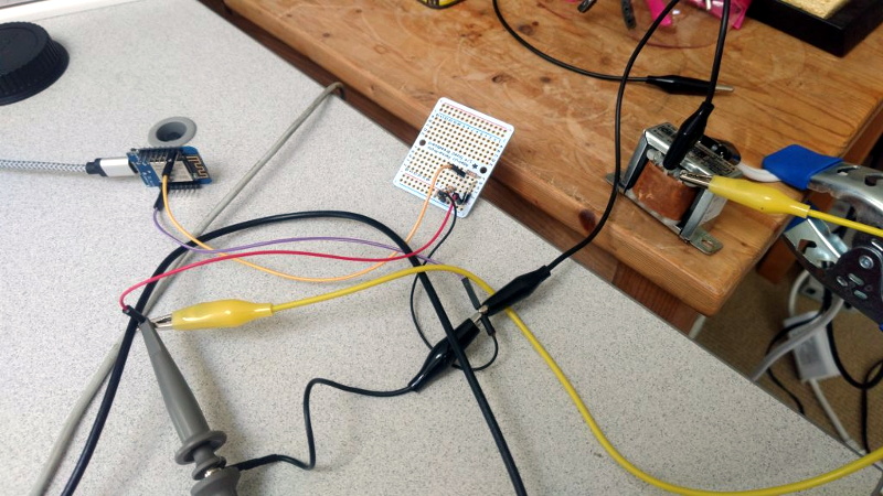
For [Nick Touran], half the work was already done. There was already a traditional wired doorbell in his home, he just had to come up with a minimally invasive way to link it with Home Assistant. He reasoned that he could tap into the low-voltage side of the doorbell transformer and watch for the telltale fluctuations that would indicate the bell was doing its thing. The ESP8266 has an ADC to measure voltage and WiFi to connect to Home Assistant, so it seemed like the perfect bridge between old and new.
Of course, as with any worthwhile project, it ended up being a bit more complicated. Wired doorbells generally operate on 16-24 VAC, and [Nick] knew if he tried to put his Wemos D1 across the line he’d release the critical Magic Smoke. What he needed was a voltage divider circuit that would take low-voltage AC and drop it to an even lower DC voltage that the microcontroller could cope with.
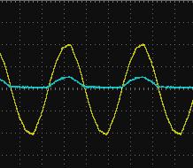
The simple circuit [Nick] comes up with cuts the voltage way down and removes the negative component completely. So what was originally 18.75 VAC turned into a series of 60 Hz blips at 2.4 VDC; perfect for feeding into a microcontroller ADC. With a baseline to work from, he could then write some code that would watch for variations in this signal to determine when the bell was ringing.
Or at least, that was the idea. While the setup worked well enough on the bench, its performance in the real-world left something to be desired. If his house guest had a heavy hand, it worked great. But a quick tap of the doorbell button would tend to go undetected. After investigating the issue, [Nick] found that he needed to use some software trickery to ensure the ESP8266 was able to keep up with the speedy signal. Once he was able to reliably detect short and long button presses, the rest was just a simple matter of sending an MQTT message to his automation system.
Compared to the hoops we’ve seen other hackers have to jump through to smarten up their doorbells, we think [Nick] got off fairly easy. This project is also an excellent example of how learning about circuit design and passive components can still come in handy in the Arduino Era.


This is weird. I would put a cap on the voltage divider and use a digital IO pin with an interrupt to detect the doorbell. Maybe also add a 3V zener to ground to cap the voltage.
Wouldn’t this make detecting short taps a bit more difficult?
That totally depends on the capacitor’s value, but this would also be the setup I would think of first. Also it is always educative to see another working method :)
If it’s so short that a uC can’t detect it it certainly wouldn’t ring an actual doorbell.
If capacitance is too large and/or current from the divider is too low, the voltage may not cross the VIH threshold on quick tap. That’s why I wrote “a bit more difficult”, not “impossible”.
Stretch the pulse with a monostable 555 and use a digital pin (with interrupt).
Very cool. Possible other method would be to wire a 0.1 ohm resistor in series, like a current shunt. Then diode-cap off that to get DC, and a resistor divider to drop it down to something the micro can handle (if necessary). Of course, it depends on what current the bell draws when ringing, so some scaling would have to be done.
How about a relay or optical coupler across the bell?
Depending on the load on the transformer and the impedance of the bell solenoid, a relay may not work as well as expected.
There is an AC optoisolator (MID400) that is great for this purpose though.
Yes, or how about an opamp peak detector with enough holdup time to be read by a digital input?
Elk Products ELK-930
So you have an electromagnetic device that taps one bit of metal against another when it’s activated? We used to call those relays — pretty easy to read the state directly. Also a reed switch against the coil windings if you’re not given to letting the spitzensparken happen directly in the klangenbell.
I was thinking about it. What seemed strange to me is that instead to check the voltage across the windings, he decided to check the current absorption in a weird way. If for some reason the transformer is changed with a beefier one with less internal resistance the voltage drop will be lower and could become more difficult to detect.
As other poster have said, using an optoisolator is another solution, or being AC using a capacitor, a diode and a zener used as 5V clamp and a smoothing capacitor coul be another solution.
Yeah why measure voltage if all you really want to measure is the current… Another more orthodox way is to use a shunt resistor and measure the voltage drop over that. Because that’s not dependent on the internal resistance.
I mean, I agree with you but regarding the transformer being changed- is that really a problem? Nobody is gonna be changing their doorbell transformer. It may not translate well to other people’s setup, but is that really relevant in a personal project?
That’s a point. Our bell transformer has been there for fifty years, probably longer. If it’s the original, it dates to 1923. The bell is newer, an old one still in place but clearly painted over.
The get a tiny bit of use even on w busy day, and always intermittent. They are hopefully well made, since nobody wants a permanently connected transformer to start burning. Most people give no thought to bell transformers, rightfully so, until it finally burns out.
The wiring is more likely to be a problem first, the doorbell in our house is connected via cloth covered twisted pair, and by now the insulation isn’t so pliable.
Michael
You can directly wire the esp8266 to the doorbell button with no ill effects as long as they don’t share a common ground.
Definitely would use an optocoupler here to isolate the door bell circuit from the ESP8266 and treat the door bell circuit as a current loop. I use a similar circuit to detect 50mSec pulses on a 24Vac line that runs 150 feet. Rather than using an ADC a simple digital I/O interrupt works well. Trying to use as a voltage loop was a nightmare with so much noise picked up, switching to a current loop made it very reliable.
I used an optoisolator for something like this, remembering ring detectors in modems use them.
And you don’t need to measure voltage, it’s a clear on/off signal. Maybe a capacitor to “stretch” the signal.
Get fancy and add a scmidt trigger. Then the cpu sees a fast rising edge almost immediately. Even a short press of the button is “long” in cpu time.
Michael
Run a wire from the doorbell down to where you can’t normally hear it, and use a beeper (sonalert). Done.
I’m about to install a tachometer on a Briggs and Stratton 18HP 31H777 engine and am thinking sniffing a similar inductive wire wrapping to couple on a positive lead would be the most basic method to use that could be tuned via the number of wraps with or without a ferrite.
I know, that’s no fun… still seems easiest even though I did make a IR Sniffer with the Arduino last night based on this instructable (https://www.instructables.com/id/Arduino-Infrared-Remote-tutorial/) and am thinking a simple current limited IR emitter inline somewhere would be sufficient as a homebrew optocoupler.
Overkill. put a relay in parallel with the bell, tie the relay’s switch to a GPIO of an ESP8266. DONE!
Check; that’s the way i did it, allthough in mu case it’s a raspberry pi zero-W because it also reads the utility meters. It has been working reliable for yeas now. As soon as a doorbell press is detected it sends it via PushOver to my smartphone and via MQTT to the home automation
Great to see so many ways to get a notification of a doorbell.
In my case, I’m already equipped with a Sonoff RF bridge. Therefore, the easiest way to accomplish this was using one of those cheap EV1527 keychain remotes to do the talking.
My example used a 12V battery as the power source, so it was a matter of short-circuiting one of the buttons, connecting an electrolytic capacitor across the battery terminals instead of the battery, wire a diode in series and connecting it across the doorbell. If somebody rings the doorbell, there will be a EV1527 RF code to trigger the Sonoff RF bridge, triggering something in Node-Red.
It seems complicated, but if you already have the infrastructure, why not use it? It could give false rings if somebody happens to use the same code, or somebody listening in, but I don’t really care about that.
I probably would have tried to use a current transformer in-line with the bell and a one-shot 555 circuit to generate a signal for the microcontroller.
You are thinking too complicated. Here is how I integrated with my home automation.. Just use a reed switch next to transformer. – https://hackaday.io/project/163815-making-dumb-doorbell-smart . Now whenever someone rings my dumb doorbell, my home automation takes the snapshot from my security cams (they are old with no AI human detection stuff) and send it to my family by telegram.
If it can detect the length of the press, the software could perhaps be set up to try to predict who might be ringing the bell. :-D
Is it really that hard? Just use two ADC inputs and compare the voltages each side of the button.
I used a 2$ AC current meter. Very very easy. Im able to detect door bell + gate open based on different current draw. I’m also able to detect special pattern on the door bell to execute specific action like open the gate, switch on lite….
Difficulty sensing when a switch is closed with an electromagnetic doorbell in series and supplied by high current 12 or 24 volt power??? (!!).
How about connecting a high powered laser led in parallel with the bell which is activated by the AC voltage with a depression of the doorbell switch. The laser is directed across the attic with a dual redundant path with a splitter and mirrors to eliminate the possibility a mouse could be blocking the beam and focussed on a black piece of machined aluminum or 3d printed PLA with a thermistor attached. A second thermistor would be nearby to sense the ambient air temperature. Both thermistors would be connected to the microprocessor’s power supply and would each be in a voltage divider with a series resistor. Each sensing node ot the two thermistors would connected to ADC inputs on the uP board and the differential temperature rise of one of the thermistors would trigger the sensing of the doorbell activation. A subroutine could be programmed into the microprocessor to count out the 30 day interval to remind to go into the attic and dust the mirrors. Make certain there are caution signs requiring personnel protective equipment laser environment eyewear for any entry into the attic…..
Just kidding. Put a reed relay across the bell and be done with it. Wire a 10 K ohm resistor from Vcc to the I/O pin and put the reed contact from I/O to ground. If needed for debouncing, put a 1uFd capacitor in parallel with the relay contact.