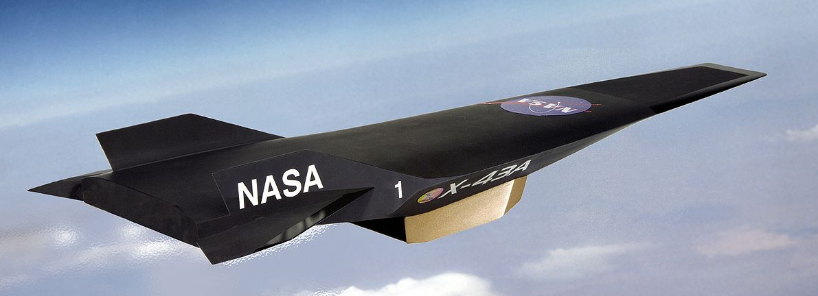
The first scramjet, an airbreathing jet engine capable of pushing an aircraft beyond Mach 5, was successfully flown in the early 1990s. But while pretty much any other technology you could imagine has progressed by leaps and bounds in the nearly 30 years that have passed, the state-of-the-art in hypersonic scramjets hasn’t moved much. We still don’t have practical hypersonic aircraft, military or otherwise, and any missiles that travel at those sort of speeds are rocket powered.
This is somewhat surprising since, at least on paper, the operating principle of the scramjet is simplicity itself. Air rushing into the engine is compressed by the geometry of the inlet, fuel is added, the mixture is ignited, and the resulting flow of expanded gases leaves the engine faster than it entered. There aren’t even any moving parts inside of a scramjet, it’s little more than a carefully shaped tube with fuel injectors and ignitors in it.
Unfortunately, pulling it off in practice is quite a bit harder. Part of the problem is that a scramjet doesn’t actually start working until the air entering the engine’s inlet is moving at around Mach 4, which makes testing them difficult and expensive. It’s possible to do it in a specially designed wind tunnel, but practically speaking, it ends up being easier to mount the engine to the front of a conventional rocket and get it up to speed that way. The downside is that such flights are one-way tickets, and end with the test article crashing into the ocean once it runs out of fuel.
But the bigger problem is that the core concept is deceptively simple. It’s easy to say you’ll just squirt some jet fuel into the stream of compressed air and light it up, but when that air is moving at thousands of miles per hour, keeping it burning is no small feat. Because of this, the operation of a scramjet has often been likened to trying to light a match in a hurricane; the challenge isn’t in the task, but in the environment you’re trying to perform it in.
Now, both Aerojet Rocketdyne and Northrop Grumman think they may have found the solution: additive manufacturing. By 3D printing their scramjet engines, they can not only iterate through design revisions faster, but produce them far cheaper than they’ve been able to in the past. Even more importantly, it enables complex internal engine geometries that would have been more difficult to produce via traditional manufacturing.
More Time to Burn
The term scramjet is short for “supersonic combustion ramjet”, which actually gives us a pretty good clue as to what’s going on inside of one. While scramjets work at hypersonic speeds beyond Mach 5, a ramjet operates from just below the speed of sound to about Mach 3. They function on essentially the same principle, but with one very important distinction: the air inside the ramjet is slowed down to subsonic velocity during the combustion stage, while in a scramjet it travels through the engine at supersonic speeds.
Not slowing the airflow inside the engine is key to the higher operational velocity of the scramjet, but it’s also the element that makes sustained combustion so difficult. Imagine a hypothetical scramjet engine with a combustion chamber that’s one meter long; at a velocity of Mach 5, air traveling in a straight line will only be inside the chamber for a fraction of a millisecond. That doesn’t give it a lot of time to mix with the fuel and ignite.
The best option for increasing the amount of time the engine has to burn the fuel and air mix, referred to as the “residence time”, is to complicate its internal geometry. Dotting the inside of the combustion chamber with small flameholder cavities gives the gasses somewhere to linger, and research has shown this greatly improves overall engine stability at hypersonic speeds.
There are a few competing ideas in regards to the shape of these cavities, but the most common approach uses indentations with a 90° leading edge and sloped back wall. According to the research paper Cavity Flame-Holders for Ignition and Flame Stabilization in Scramjets, when these indents are located aft of the fuel injection ports, the sudden drop at the front of the step creates a void in which gasses will recirculate. The angled back wall helps prevent the shockwaves which would otherwise be generated if the flow struck a flat surface after dipping down into the cavity.
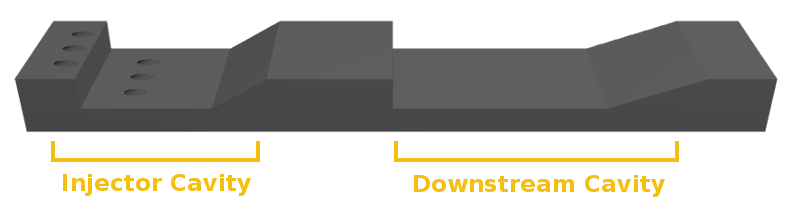
In a traditionally manufactured scramjet, these indentations would be milled into the walls of the combustion chamber. But with additive manufacturing, they can be integrated at the time of manufacture. Not only will this save time and money during the production of the engine, but it also allows for the size and position of the cavities to be experimentally adjusted. Research so far indicates that the more cavities the better, and that a “wavy” surface on the inside of the combustion chamber may be ideal.
Faster and Smaller
For the production of only a few scramjet engines, say for a small fleet of hypersonic reconnaissance aircraft, then the cost and time savings of additive manufacturing probably wouldn’t be that big of a deal. When it comes to developing cutting-edge military aircraft, history tells us the United States government is more than willing to spend whatever money is required to maintain technological superiority. But at least in the near term, the most likely application for hypersonic scramjet engines isn’t a plane.
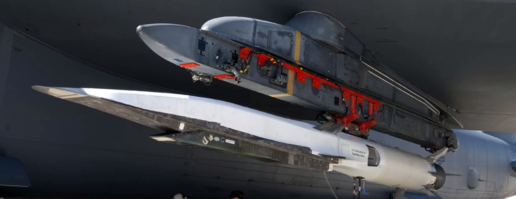
Aerojet Rocketdyne and Northrop Grumman have partnered with Lockheed Martin and Raytheon respectively to develop entries for the Defense Advanced Research Projects Agency’s (DARPA) Hypersonic Air-breathing Weapon Concept (HAWC) program, which aims to develop an affordable air-launched hypersonic missile. The program is the logical progression of the research performed during the development of the Boeing X-51 Waverider, which in 2013 set the record for the world’s longest flight of a hypersonic scramjet.
While the Waverider was successful, it was built as a technical demonstrator and never designed to be operational weapon. DARPA and the US Air Force now want to take the knowledge gained during the X-51 program and apply it to a mass-produced missile. With that shift naturally comes the need to build the engines as quickly and as cheaply as possible. There’s also a desire to miniaturize the weapon; the Waverider had to be carried aloft by a B-52 bomber, but a hypersonic cruise missile small enough to be carried by a fighter jet would be faster and less costly to deploy.
To achieve that goal, both teams have announced they are utilizing 3D printed scramjet engines. According to Aviation Week, the scramjet engine developed by the Raytheon and Northrop Grumman team is less than half the mass of the one that was used in the Boeing X-51 Waverider.
Getting Up to Speed
As you might expect with an ongoing weapons development competition, there’s a lot we don’t know about the HAWC program and its competitors. But we do know that the 3D printed engines built by Aerojet Rocketdyne and Northrop Grumman are both very far along in their development. While the exact timetable of these tests are naturally classified, DARPA Director Steven Walker told reporters in May that flight testing of at least one of the HAWC entries would happen before the close of the calendar year.
With Russia and China developing arsenals of hypersonic weapons, the United States military is highly motivated to bring their own Mach 5+ missiles and aircraft up to operational status. Some analysts believe this may be a relatively rare instance where the US is lagging behind in weapons technology, but with programs like HAWC and innovative approaches to decade’s old problems, the race may be heating up soon.


The answer seems kinda obvious,
Im gonna explain it as simply as it can be explained… Put an injector on a selfie stick ahead of the inlet. Let the compression into the first stage mix it. So when normally fuel is injected , now fuel is already in the air mixing.
How would your obvious solution prevent the combustion from propagating out the front of the engine?
It’s not always the case, buy very, VERY often, if a solution to a complex problem that dedicated engineers have been working on for decades seems obvious to a random internet user, it’s likely missing some important details.
Compressive heating would oxidize your fuel before it entered the desired burn area. Also, injecting air into a turbulent stream will lead to uneven mixing. Flow inside the jet is much more laminar. Finally, poking a stick into a mach 5 airstream is not a trivial endeavor.
Sorry, ” injecting fuel into a turbulent airstream” will lead to uneven mixing.
This makes sense and is why I posted it. ty.
Poking anything with a stick is a bad idea.
Hmmm… this comment is clearly an indication of how much “technology” has progressed. In the past (a decade ago) “addidis” most likely would have suggested a “broomstick”, but nowadays a selfie-stick seems to be more “obvious”.
Although it might be the case that a selfie-stick is much more suited for this task as they are “adjustable”. And I’m also pretty sure that a broomstick will burn to quickly or snap under the pressure… Also it is very important to remove the part with the large brush on it as it would catch too much wind.
Which reminds me… “who’s holding the selfie-stick?” (the pilot I guess)
ok so i expected better out of had, i intentionally tried to be funny saying a selfie stick, because it made the idea clear.
The tips of these are titanium like the sr71 leading edge. They come to a point. An injector embedded into the nose somewhere , seems like it would yield the correct results. Giving the fuel some time to get mixed. You dont actually need a projecting surface , because you can embed the injector into the body near the tip. The idea just sounded funnier saying a selfie stick cause i laugh at people who use them.
I just expected a bit more common sense , but that was my mistake.
I suspect that [Jan] was taking your humor and running with it, as their comment seems very tongue-in-cheek to me.
Besides, I think that a camera tripod would be more stable in the mach 5 airstream.
i hope so, there is something particularly bothersome about saying something stupid, with the intent the idea slips thru and people laugh and getting taken seriously.
Though in hindsight that was pretty dam funny. Especially since i missed it
Bit of a long-winded way to say “whoooooooooooooooooooooooooooooooosh” (the extra o’s to indicate the hypersonic nature of the missed joke, obviously), no?
I think that the selfie-stick would need an arduino or two to have the desired effect.
If it doesnt have a raspi is it really a hack? :D
Should have used a 555!
I was thinking what was on the selfie stick and stick as fuel quite frankly at first. I see em all the time at the Goodwill Stores. Call it free energy that gores to a goodwill cause, since the printing presses are already paid for I’m thinking along with the material to print the football sacks.
At least would need a really low drag design that is highly directional in injecting like the bars on the lower drag roof racks. With roof racks it will work.
Might need a different roof’ing materiel to get the buy in maybe, if your idea doesn’t work, don’t you know eh? B^)
That’s if too much no go’s and not enough go go’s.
Besides, brooms flying through the air conjures up images of witches riding them, and that is a bad image for a scramjet…
like an F1 car. https://images.app.goo.gl/r4se4zawGv7H98D87
i didnt realize it but yeah same basic idea. slightly different cause of the shape of the leading edge. But yeah.
interesting to see it done elsewhere.
Considering the response this got, I’m reluctant to ask…
If the fuel can’t mix and ignite in a 1 metre combustion chamber, why not reduce the amount of fuel?
If there’s too much air, why not make the overall tube smaller?
Tube diameter isn’t mentioned in the article – but assume it’s 60 cm (about 2 foot). Replace that with 3 tubes, each with 30cm (1 foot) diameter. After the 3 combustion chambers, you could even revert back to a single tube.
I agree, this seems like a very enjoyable problem to work. So much to try, because of the prohibitive expense of each test. That means opportunity for us to easily find things they excluded hastily. We are falling behind in this tech, we need to catch up.
“In a traditionally manufactured scramjet, these indentations would be milled into the walls of the combustion chamber. But with additive manufacturing, they can be integrated at the time of manufacture. ”
I imagine casting wouldn’t be viable?
the shapes would cause problems. i think they mill because a block is easier to pour without issues / weak spots. Then milling it would produce a more consistent end product.
At production volumes machining the features would be faster and less problematic for simple geometries.
But as the article mentions, the most efficient geometries currently appear to be fairly complex and I would think that at larger volumes you would see investment castings with some mild final machining.
The benefit of using an additive process is really prototyping speed and cost…making a single unique casting from some crazy super-alloy is time consuming and very expensive. Actually, what probably makes the most sense would be 3D printing the patterns for an investment casting.
Increasingly additive processes are being used for production as it can produce parts that are prohibitively complex to machine or cast. Additive processes are better able to control the material properties than casting in many cases. Also, there are practical limits to what machining techniques can produce in the way of complex internal features, and often if they can be machined the post processing can be error prone and prohibitively costly.
You’re totally correct and I use 3D printing in my shop pretty often, specifically to create complex internal geometries that in metal would require casting…in my case engineering plastics work pretty well.
I was going to say nobody is 3D printing exotic alloys like Inconel, luckily I fact checked myself because I was wrong.
So I guess technically you could additively process everything but for the time being, I think once the engine is out of the prototyping stage and moves into production would still involve final machining on a high quality casting.
But there is every possibility that by the time the engine is fully developed, additive processes could be viable for mass production.
You left out one important detail, and that is inspection/certification, and reduction of subassemblies that 3D printing allows.
If you have something **SPLODEY** (like a tube filled with jet fuel that travels at high speed), you want to make sure that
a) It works
b) It’s **SPLODEY** when it reaches its target (justifies the business case for building it)
c) It’s NOT **SPLODEY** before/during launch. (important detail to the pilots and the people transporting it)
Lots of aircraft manufacturers use 3D printing because it cuts lots of costs & time related to inspecting subassemblies when they are made, and then re-inspecting them each time they are joined/welded together.
Boeing now saves a buttload in time and money on aircraft engine components that are 3D printed because these parts have been made all in one operation, and only require one final inspection step, and the inspection steps for the parts and subassemblies of these parts have been eliminated.
3D printing is definitely the way to go for these parts.
“The downside is that such flights are one-way tickets…”
So, just sell one-way tickets, then. Or, make clear that the return ticket is non-refundable.
(c:
“Research so far indicates that the more cavities the better, and that a “wavy” surface on the inside of the combustion chamber may be ideal.”
Great! Raytheon just needs to set their Monoprice to 0.2 mm layers and they’re good to go.
i am pretty sure Russia developed the 3M22 Zircon without any fancy 3d printing whatsoever.
that’s mach 8-9 out of the box.
and just to rub it in a little more, the 3M22 has been in production for a while…
but go on, find more ways to inflate the pentagon budget^^
The advantages of 3D printing over other manufacturing method should be very obvious – cost, weight, and simplicity. The end prince of HACW will likely be much less than Zircon.
Additionally, if Zircon is operational then someone forgot to tell the Russian navy.
https://www.thedrive.com/the-war-zone/31908/russian-navys-top-officer-says-shadowy-zircon-hypersonic-missile-has-childhood-diseases