As [sjm4306] says, “You can never have too many clocks based on obsolete display technologies.” We couldn’t agree more, and this single-tube VFD clock is one we haven’t seen before.
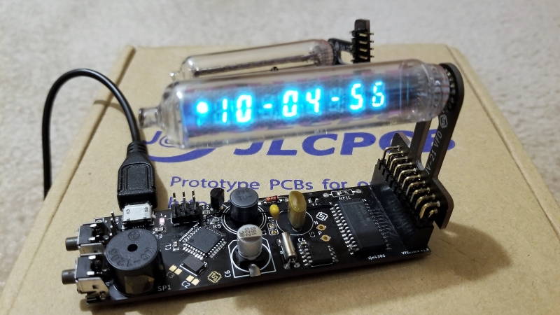
The vacuum-fluorescent display that [sjm4306] chose to base this clock on is the IV-21, an eight-digit seven-segment display on the smallish side. The tube is Russian surplus from the ’80s, as all such displays seem to be. The main PCB sports an ATMega328, a boost converter to provide the high voltage needed to run the VFD, a real-time clock, and the driver chip for the tube segments. The tube itself lives on a clever riser card that elevates the display above the main PCB and puts it at the proper angle for reading. [sjm4306] designed it to be modular; should you want to user a bigger VFD you need only make a new riser PCB. Figuring out the proper way to space the through-holes in Eagle proved elusive, but he hacked a solution using a spreadsheet to handle the trigonometry and spit out Cartesian coordinates for each hole. Pretty neat. The video below shows the clock assembly and a test.
We really like the look of this clock for some reason – perhaps it’s the quirky nature of the VFD, or the soft teal glow of the digits. We’ve featured plenty of clocks with odd displays before: VFDs large and small, faux-NIMO, de-encapsulated LED “filaments”, and lots and lots of Nixies.


Has one of these from a really old Commodore calculator, circa maybe the early 1990s.
Yup, never seen anything like it before…
Oh, wait…
https://www.adafruit.com/product/194
Yeah that’s the inspiration. Unfortunately been discontinued for quite awhile.
It’s nice to see how time flies – in a literal manner
I love the glow of these kind of displays, so any project using them I encourage.
A project where the display sticks out like this draws attention to the technology of the tube… however is also makes it more fragile. Adding additonal support to the “floating” side of the tube would not be a bad idea. It would relief the continuous stress from the solder joints and of place where the contacts meet the glass.
Although I doubt it will ever be a problem over the lifespan of this project, it should be taken into account.
Hope to see more of these kind of VFD projects, thanks for posting.
Thanks! The IV-21 is so small and light I doubt it’d be an issue. But for the IV-18 I’d definitely design supports into the case just to be safe (I’ll probably end up 3d printing something in the near future for this).
> should you want to user a bigger VFD you need only make a new riser PCB.
You are assuming all VFD uses the same voltages levels for driving and the filament (also AC vs DC). There can also be a difference to number of I/O: multiplexed vs non.
I’ve since added the ability to adjust the boost voltage in software which just leaves filament drive in question. It’d be a good idea to move the filament current limit resistor to the riser board instead of the main board though. Also for small tubes like these I haven’t seen much of an issue with dc filament drive as the gradient isn’t very noticeable, can be compensated by adjusting the grid duty in software, and simplifies the bom so I wouldn’t be too worried about it. As for I/O, the current design supports up to 9 grids multiplexed which pretty much all tubes in this size range are due to them being targeted for use in small calculators.
float – verb
be suspended freely in a liquid or gas.
… i can see an arm there :P
also, great work
Now I really want to make one of these that are magnetically floating! The big worry though would be smashing the tube when it invariably drops.
Seems indeed like a simple one. Microcontroller handles both timekeeping and a small boost converter.
The VFD itself being driven by a MAX6921 VFD Driver.
That chip is friggin awesome really. It is an easy to use Shift register with a staggering 20 outputs that can source up to 76V. A single one of those can drive an entire VFD display/clock with ease. Especially displays like the IV-21 and it’s larger version the IV-28. If one wants to play with VFD Tubes like the IV series definitely a good place to start.
Noritake still builds inexpensive VFD’s, that use logic-level inputs and provide all their bias voltages within the module. They’re lovely and Noritake even provides arduino libraries to drive them.
Totally abandoned, a shame it was a nice project…
Hello, please help with programming the atmel328. Does the bootloader have to be loaded or not? How should the fuses be set, I set them wrong and the atmel328 is blocked. Thanks Pavel.