As soon as a project involves other assemblies, parts, or modules, things get more complicated. Devices like fans, cooling units, probes, pumps, or lighting might have simple electrical requirements, but they are rarely identical. As a result, one’s tidy project ends up having to deal with, for example, a pump that is controlled with 5 V active high logic, a sensor that outputs 5 V active low, lights that expect to be switched with 24 VDC, and a fan that needs a relay right now. But that might change in the future.
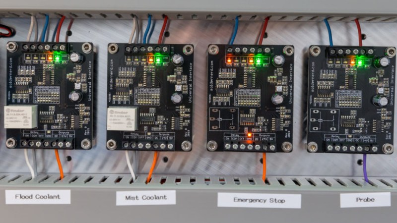
That’s exactly what led [Lukas Fässler] to design and build the Universal Interface, a board intended to be a kind of universal translator and interface for all such devices. The idea is to have one Universal Interface board for every external device. For each board, a wide variety of input combinations controls a single output. The boards are “hardware programmable” in the sense that jumpers (zero-ohm resistors) are used to spell out in black and white exactly what combinations of inputs result in which output state. In this way, some standardization and clarity of control can be enforced while still being flexible enough to accommodate changes.
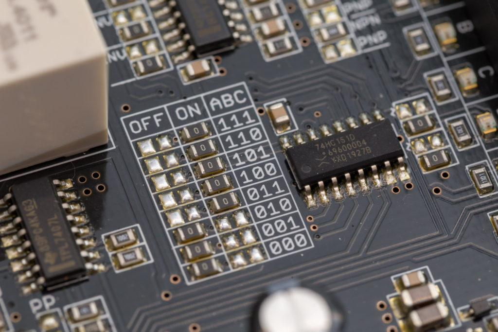
Each Universal Interface board has three inputs and an enable line, each with their own indicator LED visually confirming its state. The inputs are 24 V tolerant and each can be configured with a pull-up, a pull-down, and as an active high or active low. There is one output, but it takes several forms: a sturdy relay, a powerful open-collector output, a 5 V logic output, and a 24 V logic output. Configuring which output state corresponds to what combination of inputs is set by jumpers, so the board is very much WYSIWYG.
[Lukas] is currently using four of these devices with his CNC mill project, all in different configurations, and they’re working reliably. Interested? The GitHub repository for the project has all the board design files.


Looks like the attention from this article overloaded the author’s page – getting a database error
fixed now.
I really like this design because it’s KISS – keep it simple stupid. No need to program any microcontroller or PLC or FPGA – just off the shelf parts and good ol’ CMOS logic. And the PCB looks well designed too. Not sure why he didn’t go for dip switches instead of resistors to set the address.
My guess is he wanted a design that could quickly adapted and then set to a somewhat static configuration state. dips and jumpers can, naturally, be quickly changed– which is a good thing if you want something to change quickly, and bad if you dont wan’t to change something quickly. for motion control systems like his CNC application, you typically don’t want these things to change unless you really want them to change. Accidental changes could lead to disastrous effect, and some masochists like doing homebrew SMD soldering
“The factory of the future will have 2 employees, a man and a dog.
It will be the man’s job to feed the dog, and the dog’s job to keep the man from pushing any buttons.”
You mean a bit like a PLC….
This is nothing like a PLC. No programming involved, far lower complexity, you know exactly how it’s configured just by looking at it, and anyone can reconfigure it when the PLC guy buggers off.
“and anyone can reconfigure it when the PLC guy buggers off.” You might be surprised how many people in a maintenance / operator position that can’t even follow and figure out a relay control logic consisting of less than 10 relays.
>>No programming involved<<
Soldering the 0 Ohms is a kind of programming
“My favorite programming language is… solder”
–Bob Pease
Nice! Pcb looks well designed.
I would replace those solder jumpers with a dip switch or something more easy to configure.
That emergency stop would be illegal here in EU.
Good catch. Bad practice to have an E-stop be electronics. What happens in a voltage surge or a brown out? Both of those are situations where you might want to hit the E-stop.
I give hime a tripple A double plus good for effort.
Website looks nice, lots of pictures, nice explanation of what he’s done, even links to github.
However, I could not find a schematic (in a universally readable format), and I am a guy who prefers to see a schematic above reading pages of text. 20 pictures of the board aso do not help much.
His Github project seems to be eagle (which I do not have) and no pdf format.
Tip: Always add a pdf (or even png) of your schematics to the documentation. Not everybody has your particular PCB program, and having a pdf is very hand if for example the license of your expensive software expires (changes, internet rolls over, whatever) and you are not willing to buy a new one.
I could try to import it into KiCad, but as I have another work flow as the author of this project, I won’t bother myself with this.
For one-time oddities I usually just solder them with old fashioned wired components on a piece of veroboard. It looks kinda ugly, but it’s robust and reliable.
For any more complicated logic (even if it fits in a NE555) I just grab a microcontroller for the sheer ease of changing the way it works by just massaging my keyboard, and I do not have to be carefull which side of the soldering iron I hold in my hand.
Also: You can buy very nice PLC boards from Ali / Ebay / China, starting below USD20. (Just saw one for USD16 with 4 relay outputs)
These boards have a nice SMPS with extra common mode fitlers, optically isolated inputs (Any voltage by adding / replacing a resistor) and outputs with either relays or transistors.
These PLC’s also tend to have an STM32 in it, so you can reprogram then in a decent way with C++ instead of fiddling around with archaic and obsolete ladder logic.
If you’re interested, use “FX2N” or “FX3U” as magic search words.
The board I bought also has a serial interface (with DB-9) and a RS485 driver to make a network of these things.
PCB’s also seem to be well made and with pretty reasonable layout (GND planes, Isolation), but this may vary as probably many vendors sell these boards.
The only disadvantage I’ve found on the board I bought is that the RS485 driver is an SN75176 which is not a very robust chip, and there is no protection (TVS, etc) on the board for RS485 whatsowever.
Some final tips:
– Think about the connectors you want. I prefer the robust green pluggable connectors, but the’re less cheap.
– You can also buy the PLC in a plastic box for a few EURo’s extra if you like.
– You can also add modifications: Desolder a few of the Power transistors (Some have an ULN2003 to drive relays) and attach any circuit you like.
Change the configuration to dip switches, add 4-20mA input for industrial sensors, and PWM output for speed control etc, then pack it into a DIN rail mount enclosure and you have a killer product.
Don’t forget modbus.
Preferably if he also gets it certified. Like a stock Arduino vs controllino.
He probably doesn’t trust the reliability of DIP switches in a possibly dirty environment.
Solder bridge pads or solderable jumper wires?
Call me stupid but why do you need 8 switches to configure a 3 bit logic word?
What happens if there are more than 1 resistor jumpers set to ‘on’ by mistake?
The person obviously doesn’t know about 74xx688 8-bit magnitude comparator. :P
Woosh. :( That’s a painful and expensive way for setting a truth table lookup. Might as well do relay logic. :P
Looks like that would short the normal and inverted outputs of the multiplexer, almost certainly exceeding the 25mA output current spec in the datasheet.
It isn’t a 3 bit logic work, it’s a truth table to derive a one bit output (the ON or OFF resistor) based on all the possible (8) combinations of the three inputs that the device has.
That’s not what’s going on here. For the 8 possible combinations of inputs, the switches determine whether the final output should be on or off. Essentially, they let you set up a custom logic function with 3 inputs.
I think some people are missing the point… I am pretty sure I see why the original poster did this and it makes sense to me at least.
I can’t tell you how many little proto boards I’ve populated with just a gate driver for a MOSFET/IGBT, or a relay and ita drive circuit, or one of those little 6-pin logic level shifters. For quick hacky/temporary experiments this is OK (especially if you label, save, and reuse these adaptors) but I’ve been tempted to make them in batches too.
In fact, I _have_ made a small batch of a building block I found myself needing often (takes a 1.8-12v input and splits it and on each leg of the Y is the common pattern of pairs of small bypass caps on either side of a pair of ferrite beads) as one commonly used to keep switching noise from the digital side from spewing into the analog side. It’s really nice to have a building block like that to prototype with.
Yes please to 4-20ma. I wish this was around a few years back, would have made my life a lot easier. Good work!
This reminds me of the controller board for a pick and place I wire wrapped for my job back in the 1988 or so . They used a stepper controller chip (forgot the chip) and kept blowing the 2n3055 output transistor until I swapped the NTE brand for a Motorola brand . Those NTE ones were always trouble as they seemed binned from rejects and sold as good enough
Standards
https://xkcd.com/927/
This is awesome! We’re going to put this up on inspectAR for anyone to use…. no need to open the schematic or board layout to figure out what’s connected to what. Makes it much easier with a purely hardware-programmed setup like this. Should be up there shortly :)
oh hello there, mihir!
oo security error certificate failure. nice.