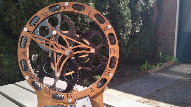
A clock is perhaps one of the the most popular projects among makers. Most designs we see are purely electronic and do not bother with the often more complicated mechanical part. Instructables user [Looman_projects] though was not afraid of calculating gear ratios and tooth counts for his planetary gear clock.
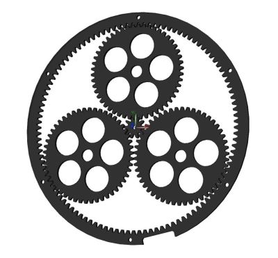
As shown in the picture, a planetary gear, also known as epicyclic gear, consists of three parts: a central sun gear, planetary gears moving around the sun gear and an outer ring with inward-facing teeth holding it all together. The mechanism dates back to ancient Greece but is still being used in car transmissions and has become quite popular in 3D printing. In his instructable [Looman_projects] has some useful inlinks including an explanation video of how planetary gear sets work and a website helping you to calculate the tooth counts for specific gear ratios. It is also noteworthy that he tried to cut the gears from aluminum with a waterjet which unfortunately failed because the parts were too small. What makes the clock visually stand out is the beautiful ornamental see-through design of the dial plate and hands made from laser-cut wood. Despite the mechanical gearbox, it is not surprising that the driving mechanism is based on ubiquitous pieces of digital electronics including an Arduino Nano, DS3231 RTC module, and a stepper motor. To avoid a cabling mess [Looman_projects] designed a custom PCB that interconnects all the electronics and says he even got some spare PCBs left for people interested in rebuilding the clock.
Actually, this is not the first laser-cut planetary gear clock that we have seen. In case you are wondering about the advantages of planetary gearboxes, you might want to check out how a 3D printed version is lifting an anvil.


I love it, and am now very tempted to make one.
The video itches my brain somewhat because the minute hand and the hour hand disagree about when they’re on the hour.
Surely that’s just an alignment issue. Easy enough to fix by backing off the centre screw and rotating the minute hand a couple of degrees.
Fantastic clock though. If I had access to a laser cutter I’d be making one for sure.
Yes it absolutely is just an alignment issue, that’s why it’s just an itch. I would have to fix it immediately because I’d keep thinking about it otherwise.
Wow, that’s a nice looking clock. Well done! Great concept dial/gear arrangement.
Wow! This is lovely! WANT! I wish the editors had included the upgrade to my original planetary gear clock that even has a second hand (only one motor) https://wyolum.com/evolution-of-a-gear-clock/
Looks good, and now I wonder if a NC router is good enough to do it.
I can’t get over that wart of a motor at 5:30 though. That really needs to go on the backside.
I kind of like the motor placement the whole design is skeletal – As everything of how it works is visible its quite inkeeping. I would not have made the PCB or motor visible in that way if it were my project though. If keeping the skeletal look I think the PCB would be the face and the motor mounted axle pointing up as part of the stand area – so its still visible but a central part of the mount.
As for making something like it scale it up or down somewhat to fit your tools and materials and it will be easy enough to make, its a very simple design. Could be done with hand files and a paper template if you wanted to.
Excellent !!!!