When it comes to manufacturing, sheet metal and injection molding make the world go ’round. As a manufacturing method, injection molding has its own range of unique design issues and gotchas that are better to be aware of than not. To help with this awareness, [studiored] has a series of blog posts describing injection molding design issues, presented from the perspective of how to avoid and address them.

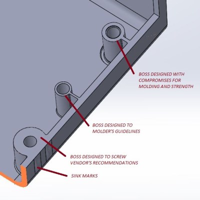
Because injection molding involves heat, warp is one issue to be aware of and its principles will probably be familiar to anyone with nitty-gritty experience in 3D printing. Sink marks are also an issue that comes down to differential cooling causing problems, and can ruin a smooth and glossy finish. Both of these play a role in how best to design bosses.
Minimizing and simplifying undercuts (similar to overhangs in 3D printer parlance) is a bit more in-depth, because even a single undercut means much more complex tooling for the mold. Finally, because injection molding depends on reliably molding, cooling, and ejecting parts, designing parts with draft (a slight angle to aid part removal) can be a fact of life.
[studiored] seems to have been working overtime on sharing tips for product design and manufacture on their blog, so it’s worth keeping an eye on it for more additions. We mentioned earlier that much of the manufacturing world revolves around injection molding and sheet metal, so to round out your knowledge we published a primer on everything you need to know about the art and science of bending sheet metal. With a working knowledge of the kinds of design issues that affect these two common manufacturing methods, you’ll have a solid foundation for any forays into either world.


Nice dude, I appreciate a lot that you have shared this.
I recently repaired a laptop with screw bosses apparently designed to molders guidelines. Very thin plastic around the metal inserts for the lid hinge mountings. Much super glue and JB Weld went into the back corners of that computer.
Sink marks aren’t a problem if the molder sets up the machine to pack and hold long enough for the mold cooling to chill the shot solid. It does increase cost due to the increased cycle time from having to cool the mold down more, then heat it back up for the next shot.
Cheap plastic items get the mold packed full, no holding, and cooled just enough that the items won’t collapse under their own weight when they’re ejected. That reduces the cycle time through needing less heating up between shots.
Injection molding silicone needs the opposite. Molds have the be COLD when being filled, then rapidly heated to accelerate the action of the catalyst that cures the silicone.
Sorry but that is not really correct. It is not on the molder about shrink marks. Most likely it is the design of the mold. The pressure from the inlet doesn’t reach the specific area or o thinner part already got solid and the holding pressure is excluded to this area. So many other reasons are possible. However your explanation could be also one of those.
Injection molding Process Engineer here… Even when producing “cheap” plastic parts, fill and pack/hold stages are utilized to minimize sink. Ultimately, it comes down to the standard cycle time set for the tool, and the quality standards set in place by the end user. Always a delicate dance between the two.
Very much this. I’ve seen fights break out between process techs and quality inspectors. Usually cause the tech said it couldn’t be fixed and the inspector insisted.
There are literally dozens of different things that can cause the same visible problems in injection molding. That’s not even counting the invisible problems (bubbles in thick parts, lamination,weak spots that don’t crack till it gets cold, etc)
for some interesting read https://www.protolabs.co.uk/resources/design-aids/injection-moulding-for-dummies-e-book/ Helped me quite a bit with understanding foc
Don’t you just hate it when they design bosses to screw vendor’s recommendations?
Maniacs, passive-aggressive maniacs.
Injection-Mold Engineer: “Grrr, if there’s one thing I hate in this world, it’s vendors! Sticking their long vendor noses in other people’s injection-molding business, making fancy vendor recommendations! I’ll send them a message they will hardly be able to notice on close inspection…”
Vendor, several months later: “Good lord. Look at that boss! We were just trying to be helpful….sheesh, injection-molders…”
I only scrolled down to the comments to see if someone made this joke, and I was not disappointed.
In the sheet metal stamping world I found this book to be hugely insightful: Die Makers Handbook by Jerry Arnold. It’s aimed at the person who takes the paper design for a die stamp and actually makes the die from it. He clearly demonstrates many years of experience of die making here by outlining similar problems in the metal stamping world. He also covers solutions to these problems, such as using the tolerance specification as a way to overcome deficiencies in the on-paper design while not otherwise altering the design.
I highly recommend this book if you plan to design die stamped parts, it will help make parts that are actually capable of being die stamped correctly and reduce your headaches over the long run.
Interesting suggestion, I have no immediate need for that knowledge, but you never know when information will come in handy.
Always looking for more for my machining library, which is regularly referenced.
This is actually a fantastic layman’s guide to designing tooling for injection molding and taught me a lot on just a lunch break.
I’m a tool & diemaker myself, but I make forging dies, and some of this is incorporated even into our forged parts.
Very cool.