Give your grizzled and cramped hands a break from stuffing boards with surface mount components. This is the job of pick and place machine, and over the years these tools of the trade for Printed Circuit Board Assembly (PCBA) have gotten closer to reality for the home shop; with some models diving below the $10,000 mark. But if you’re not doing it professionally, those are still unobtanium.
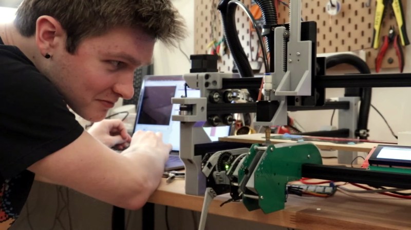
The cost of this one, on the other hand, could be explained away as a project in itself. You’re not buying a $450 shop tool, you’re purchasing materials to chase the fever dream of building an open source pick and place machine. There are two major parts here, an X/Y/Z machine tool that can also rotate the vacuum-based parts picker, and the feeders that reel out components to be placed. All of this is working, but there’s still a long road to travel before it becomes a set and forget machine.
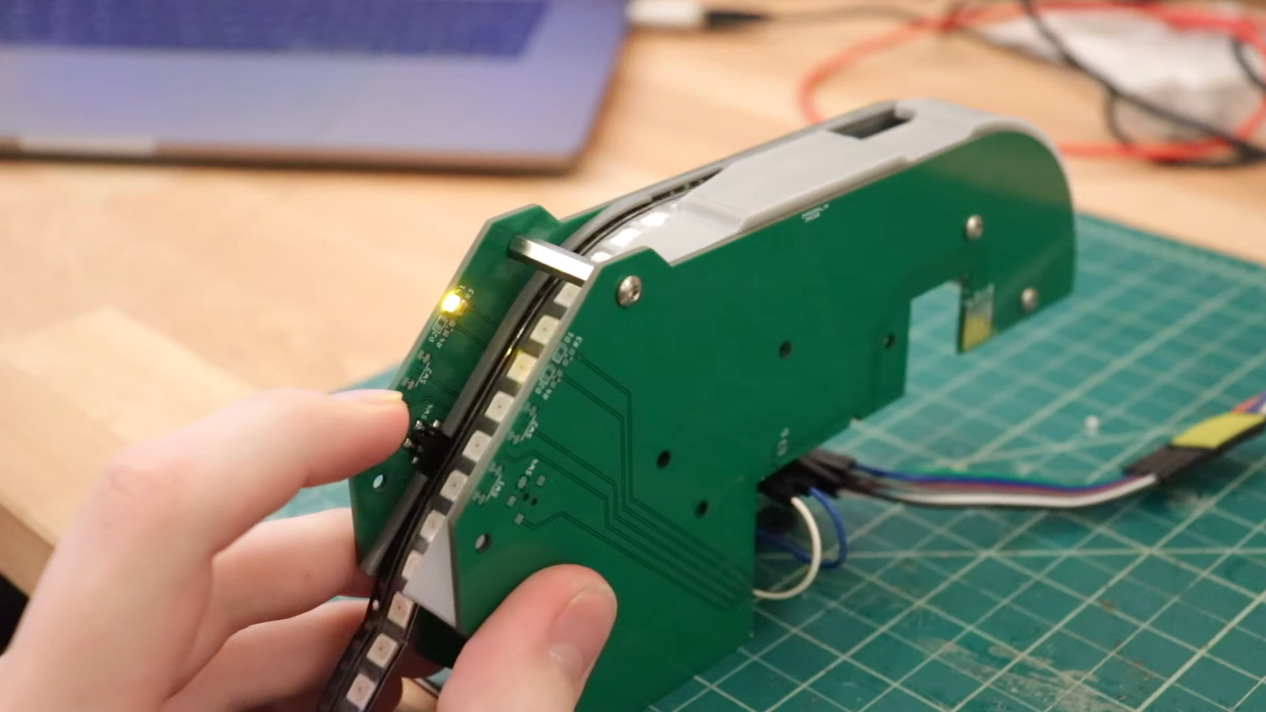 The rubber hits the road in two ways with pick and place machines: the feeders, and the optical placement. The feeders are where [Stephen Hawes] has done a ton of work, all shown in his video series that began back in January. The stackup of PCBs and 3D-prints hangs on the front rail of the gantry assembly, is adjustable for tape widths, and uses an interesting PCB encoder wheel and worm-gear for fine-tuning the feed. [Stephen’s] main controller board, a RAMPS shield for and Arduino Mega that runs a customized version of Marlin, can work with up to 32 of these feeders.
So far it doesn’t look like he’s tackled a vision system, although the Bill of Materials does include “Downwards Camera”, confirming this is a planned feature. Vision is crucial in commercial offerings, with at least one downward camera for precise board positioning, and often an up-facing camera as well to ensure component position and orientation (if not multiple cameras for each purpose). Without these, the machine would be dead reckoning and that can lead to drift over the size of the board and the duration of the placement run as well as axial misalignment. Adding vision shouldn’t be a ground-up effort though, as [Stephen] chose to use OpenPnP to drive the machine and that project already has vision support. This will be much simpler to add when compared to the complexity of the feeders.
[Stephen] admits that much work still needs to be done and he would love to have help dialing in the performance of the feeder design, and fleshing out features on the road to perfection. Although we suspect that as in the early days of bootstrapping 3D printers, a project like this can never be truly finished. At least it’ll make his next run of LED glowties a lot easier to fabricate.
[Thanks Nils!]


Smoothieboard is the official controller for the OpenPNP stack. You can get RAMPS to work, but it’s not what’s most supported/dev for.
We’ve added/modded quite a few things over the years based on the feedback of the OpenPNP project/users.
OpenPNP RAMPS support is more a way for people who have a RAMPS laying around to use it for something.
I considered building my own SMT machine but I bought a machine from Madell instead. It cost me $14,000 but the machine includes the part rotation, up vision, down vision and their feeders do a good job. Sometime it comes down to a time verses cost decision and I made the right one. In the last 6 years I’ve owned the machine the time saved has more than covered it’s cost.
Also concerning reflow. A toaster oven makes a great reflow oven. I used one for years before upgrading to a $300 desktop temperature controlled reflow oven. And then I discovered that the toaster oven works just as well!!!
OpenPNP supports all that as far as I remember.
Nice if you have 14K
the feeders have always been a pain point for these things. First blush this looks like a good one. Best pick and places will go with something like an odrive and servos. I’m waiting on a machine for like $4K that has good feeders and 0402 size part placement with a servo.
You can spend an enormous amount of time on these things and in the end it may be better to just hand assemble or utilize a manual pick and place or human in the loop pick and place for the first few times and then pay an assembly house to do that rest. I’m one an evaluation now. I may update later.
I’m going to make a feeder which only requires you dump a bunch of parts into a flat container. Use ocv to id the orientation and pick up. If the part is upside down, auto jiggle, while the head is off placing a part (Use an auto sliding cover), or pick and drop until it’s correct (probably would use less operator time than setting up trays). This gives fast setup, more “feeders” (based on gantry area though…maybe use a conveyor to reduce footprint.)
For me a PNP is of limited value – I very rarely do more than 20 of any board, most of the time I’m doing the 3 that I got from OshPark.
So instead of PNP what I really want is PND – Pick and Drop, a machine that is driven by voice command where I simply ask for some number of a component and it magically shows up at a designated spot on my workbench.
Alexa, get me 6 100 nano 0603 caps
Hey Google Get me a 10k 0603 resistor
Even if it were just limited to chicklet parts it would save me a ton of time.
I like that idea, hopefully it would be able to drop components the right way up. I swear, an 0402 resistor has 12 white sides and one black side when you’re trying to flip it right side up with tweezers.
yea, for whatever reason, they always tend to land peanut butter side down. Statistically it doesn’t make sense
I’ve hand-loaded a _lot_ of very large boards (500+ components each on dozens, maybe hundreds of boards) and I’m pretty sure this is confirmation bias, because while I agree that it seems this way, I’ve also spent time counting how many parts are black side up and how many white side up when I jiggle the container they’re in, and it’s just about 50%. I think it looks worse than it is because most of the time you look in, you see more upside down parts as a result of having already pulled out a bunch of the right side up parts.
That’s true, but if there’s no markings on the part (like 0402 and some 0603), does it matter which way up you solder it?
Most SMD resistors have the resistive element on the top side of the chip. Mounting it upside down can degrade the power rating by reducing air flow for cooling. It’s possible that it could also compromise mechanical strength of the part during vibration of the PCB. That being said, I happily solder them in upside down and backwards for prototyping in the lab but not when others are going to be inspecting my work.
That’s true, but we’re talking about hand soldering 0402s here, so it’s not exactly volume or high reliability production.
and actually, I don’t have a feel for it, but it could be that the thermal dissipation of the resistive layer being closer to the thermal mass of the pads and traces is better than the air….. how to test?
That’s because as things become smaller, all those folded up dimensions come into play.
I like the idea too, but you cannot possibly get a feeder for every component. So you’d need to get some sort of mint dispenser or something and a robot to fetch and dispense.
“That’s because as things become smaller, all those folded up dimensions come into play.”
(chuckle)
If you need many of the same kind, just throw some on the desk. Pick and place the ones that land the right way, until they are all upside down. Then press down on them with a finger tip to lift them up, and then rub them off. Place the ones that fell the right away. Repeat.
If you need just one or two, I find that using a rubbery anti static mat works well to flip them. Gently push down on the edge with tweezers to make them flip.
Another option would be to put them in a small container that’s open at the top, and some kind of metal clicky dome underneath so you can push down and make them all jump up.
put them on an piece of paper, tap the paper with a finger and they jump
And they jump onto the carpet!
FTFY
B^)
It works either way.
I made some kits for a DIY hand build SMT project years ago when I was also partially in charge of the Fuji CP6 PnP machines where I used to work. I created a program that placed parts on a “board” that was an array of 3×5 cards printed with the silkscreen of the picture of the PCBA which was then covered with a PCBA sized piece of doublesided tape.
The program neatly placed 14 different parts on each card where they need to be on the PCBA and 4 “spares” along one edge. When done, I had a card with the parts needed for the builder and “directions” to follow for hand placement. Smallest part was 0805, so it was very easy. The hardest part was making the “boards” with all that doublesided tape. Last, I would cover each “board” with clear material (used old sheet protectors) to keep the parts in place and cover the sticky. Squeezed it all into a 3×5 ESD bag for shipping. My customers loved it, but my employer shut down the site I was working at, so additional orders got shelved while I hunted for work.
I always wanted to replicate the idea with a container that worked like a plastic parts container. Drop each part into a cavity per the BOM and the close the top (obviously with a compartment to compartment seal). Unfortunately, most of my products lately have not quite supported the DIY Kit model (not everyone cares for QFNs)
Nice idea. For the cavity approach, a card bottom layer, laser-cut corrugated cardboard, plastic top layer might work well
or vacuum formed plastic sheet made into a tray with part recesses built in?
just make an alexa skill for this if that what you want. https://hackaday.com/2020/01/26/light-the-way-to-every-component/
You can always pay for some assembly service…
Also:
Mike has got a second hand but professional Pick and place machine, but still uses hand assembly.
He says that for small batches using hand assembly is faster then setting up the SMT machine.
He also has a 15 minute video chock full of tips for hand assembly:
https://www.youtube.com/watch?v=pdGSFc7VjBE
I just want more highly integrated parts available in SOIC. Particularly missing is an equivalent of an FPGA for power handling. Just make an I2C controlled, hand solderable device that can buck/boost charge, provide one or two buck/boost outputs, and do some ORing logic for nano grid stuff.
But sadly it’s all BGAs….
So many designs could have like, a third of the parts if we had more mass produced configurable analog gear. Where’s the 60v capable ESD protected ADC/amplifier/comparator chips?
I work in analog power design. Nobody large is willing to pay for any more than the bare minimum, and it’s extremely difficult to make a convincing business case for broad market parts. Depending on the pricing structure, we have to sell half a million parts just to break even on development, so if you can’t make a convincing case for that, it won’t get approved. (And when I say bare minimum, I mean we’ve put parts in production, and had possible customers say “I don’t want to pay for all that extra stuff” and we “spin” the die by doing literally nothing but putting a different marking on it and making a data sheet that doesn’t mention the functionality they didn’t want, and cut the price a little, and they buy it. If they buy enough, it’s worth the price cut to us.)
We have an i2c chip that has multiple buck/boost controllers in it. It’s extremely difficult to market because the people who mostly want it are hardware people who completely glaze over when you start talking about how to set up the registers to control the phase relationship between the different channels. On previous chips like this, we’ve spent something like 70% of our engineering time supporting software required to demonstrate the unit, and supporting customer designers trying to use it, compared to the 30% we spent developing it, and again that’s expensive and even harder to recoup because it isn’t a one-time expenditure. It’s like a continuing cost that rises with each new purchase.
It’s also a little difficult (not at all impossible, just inconvenient) to do a lot of digital stuff in higher voltage processes. It takes up a lot of die space because of the process requirements.
Oh wow, I never knew any of that stuff about chip design!
I work in small quantity and mostly consumer-level complexity, often as the only only engineer, so my first order of business is to replace every single component I can with software, no matter how much complexity it adds. More hardware means more things to fail when if it gets abused, and more things to mess up when you only get one try and getting boards made because of schedule, plus hardware is fixed, and half the time someone wants the design built before they even know what they want.
I wasn’t aware HW engineers hated dealing with registers so much! I guess it makes sense though, I’ve even met software guys who really don’t seem to like software too much. A lot of engineers seem to prefer things they feel like they understand down to the lowest level.
Sure does seem like the issue could be fixed with enough economies of scale though. If we just has a fully integrated “default choice” that everyone agreed on and could make by the billion, the same way 555 timers and 7805s were everywhere in everything for a while, I’m sure someone would figure out the cost issue.
Not that anyone seems to want to standardize anything these days! Everyone seems to hate standards and prefer their ad hoc “Perfect for for this one application” solutions, at least in software.
How about using a reverse image of the placement,
place the components upside down on a sticky “plastic” sheet over the reverse image,
place the sticky sheet, with all the components properly oriented, on the pre-solder pasted circuit board,
send it into reflow,
Badda-boom, Badda-bing!
A PCB with components AND conformal coating!
(I’ll see myself to the door now)
Use the ones that land wrong-side down on the other side of the board. (Sorry, couldn’t resist recycling an old joke.)
At what point do PNP machines typically save labor, in terms of number of boards made? I occasionally need to make 20-30 of designs, but frequently make 1-5. Professional assembly is generally too expensive for a hobby project until 50-100 boards. JLCPCB’s assembly service is cool, but it seems risky to base a design on it given the limitations (e.g. no way to request them to order more of an out-of-stock part).
It really depends upon the quantity, type of components, and the number of different parts. Setting my older Juki takes anywhere from 1-4 hours to set up (e.g. feeders, programming, etc) and so it makes no time sense to do this for a couple of boards. However, if you have your PnP setup with components you regularly use (caps, resistors, etc) then the setup time can be reduced dramatically. On many occasions I use the PnP to populate the standard parts that I have already setup on the machine and then I manually place the remainder of the parts. Doing it this way I would save about 60-70% of the time as compared to hand populating the entire board. If I have to assemble more than 20-25 boards I usually send these to my contract manufacturer (CM), as they can do it faster given that they have new equipment. However the leadtime for my CM is about 3-4 weeks and so if time is critical, then I will run my PnP and do even larger runs in house.
I applaud those who choose to design their own PnP machines, but I have to ask if it would not be better to buy an older professional PnP and then retrofit it with OpenPnP, etc? This way would provide an excellent starting point with many of the mechanical details taken care of along with the supply of various feeder types, etc? Feeders are critical to a PnP’s use and if you looked at commercial feeders, you can see the complexity of these devices and so using these off the shelf items will save a ton of time and best of all you can buy as many as you need… and in some cases for far less than making your own.
That’s definitely something people do. I’ve helped ( on the smoothieboard side of those projects ) a dozen people do that the past year or so. Interrestingly, often the machines are much more capable *once* converted to OpenPNP, compared to the DOS software they came with.
Indeed, I have seen a few do this. However, a lot of people decide to build everything from scratch… which is a ton of work with variable results. The full custom PnP will have some level of feeder limitations (quantity, types, etc) and not too mention placement speed. Using a professional machine as a base would really elevate the results… and would no doubt be faster to create.
Yes, but then it isn’t open source. This benefits more than himself, and as we know society grows great when people plant trees whose shade they know they will never live to sit in.
Actually it would be open source… as my comment was about using OpenPnP and a controller board but using the original equipment infrastructure… in other words, it would be hacking it to do your bidding. As I said, making your PnP is great, but in the end its usefulness varies, as there are a lot of items to consider. Until I got my own PnP I never considered all of these details and as such that is why I would highly recommend to start of with a existing older unit with all of its infrastructure in place and go from there. Doing this would result in a much more versatile and useful device. Before anyone goes off on making their own PnP I would suggest you have someone walk you through all the steps in setting up and operating a PnP… there is a lot more to it than simply picking a part and placing it.
If your goal is to have an affordable and working machine in a short time, buying second hand is very likely a better option than building yourself.
If you are on a very tight budget, do it for a hobby and see building a machine from simple parts as a fun challenge or as a learning experience of how it all works, then buy some parts and build it yourself.
Also, the Chinese build table-top machines of about the size as in the video above and you can buy a new machine for prices starting around EUR2000 or EUR3000
English menu’s for the built-in LCD are optional though. Maybe you can strike a deal and buy just the mechanics if you want to run it on openPNP.
I started making a rotatable vacuum nozzle. I have more concepts but they are unlisted on my channel.
https://youtu.be/z7TM1tV7PzM
Just wondering if those froopy cheap “USB keyboard vacuums” pull hard enough for small component handling, or are they complete gossam?
I spent a while searching for vacuum pump options when getting a manual pick-and-place system up and running.
I ended up modifying an aquarium air pump.
Someone documented the procedure here: https://www.instructables.com/id/Vacuum-Pump-from-Aquarium-Air-Pump/
Whether you can pick up a part depends on:
* The weight of your part (almost nothing)
* The “effective” diameter of your nozzle.
* The pressure differential of your vacuum.
With a perfect vacuum you can suck about 10 meters of water through a tube.
Then some back of the envelope assumptions:
* Specific weight for ceramic components of 3 times that of water.
* Underpressure of 10kPa
* Size ratio of your nozzle to component of 1:10
Then you can still lift a stack of components 3 cm high.
So almost any vacuum pump will do.
However, with a bigger pressure differential the size of your nozzle is less critical, an you can for example pick up 12*12mm QFP’s with the same nozzle as a 1206 resistor. With such a high ratio reliability and accuracy goes down though. Components may move in transit through vibrations.
Thanks folks, though I’m not after the best vacuum pump, more a cheap, light, low power vacuum that a semi-autonomous little bot could use as it wanders around your bench and grabs things for you. Or auto-tidies a random pile of components into types or something.
Just consider it a deliberate under-design to allow a concept to get tested rapidly and evolve generatively as you let it find out what it’s good at, before you get your feet nailed to the floor by scope creep. Plus crappy quirky things that work with a dozen niggles are far, far more fun than something you work months on to be perfect and have a single problem that only a crappy, quirky bandaid can solve in the end.
But I’m just running brain simulations at the moment.
> So far it doesn’t look like he’s tackled a vision system, […] Without these, the machine would be dead reckoning and that can lead to drift over the size of the board and the duration of the placement run as well as axial misalignment.
Wait what?
There are tons of systems out there that position repeatably to 0.01mm over areas larger than hobby PCBs, or even professional PCBs, often using completely open loop “dead reckoning” steppers and basically *never* using computer vision. CNC machines. Even 3D printers. Machine vision seems like a massively Rube Goldberg approach. Cut your board accurately and clamp it in a corner.
What am I missing here? I’m sure there must be something, but I have no *clue*.
You are missing the random variation of the part inside the tape. For large parts it isn’t a problem but the smaller you get the harder it is to pick up a resistor close enough to the center to work.
A while ago, I fixed a bug that caused Arduino mega support not to work. (It seems many have these, and they are cheap with lots of io). Do you know if it still works with Arduino mega?
(This reply was to the first comment, wrt openPNP Ramps vs Smoothie board.)
I want to know which are the other communication board for this open PnP like TinyG
Can I use the mach3 CNC machine board for openPnP
Smoothieboard is the official control system for OpenPNP, it’s the one the documentation is written around, it’s the one the dev is done around, it’s the one that’s going to support the most advanced features as a consequence, etc. TinyG works, it’s just not as easy/supported.
For Mach3 I’m not sure, that sounds like it’d have some limitations, but the best you can do is to ask in the OpenPNP Google Group, they’ll know all the answers there.
Stephen maintains the JOY of developing something and seeing it work. His enthusiasm is contagious and inspiring. He also shows his failures.
Have watched all of his videos and enjoyed them all.