It’s hardly a secret that getting into a serious electronics habit can be detrimental to your bank account. A professional grade lab is simply unobtainable for many a tinkerer, and even mid-range hardware can set you back considerably. Which is why many folks just starting out will attempt to salvage or build as much of their equipment as possible. It might not always be pretty, but it’ll get the job done.
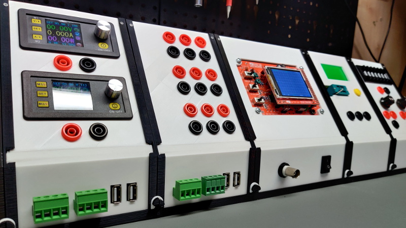
But this project by [Chrismettal] could end up completely reinventing the home electronic workspace. Using 3D printed frames, low-cost components, and a sprinkling of custom PCBs, this modular electronics workbench has all the bells and whistles an aspiring hardware hacker could need. As an added bonus, it looks like something that came off the International Space Station.
This is one of those projects that simply can’t be done justice in a few paragraphs. If you’ve ever wanted to put together a dedicated electronics workbench but were put off by the cost of individual components, read though the fantastic documentation [Chrismettal] has prepared for the EleLab_v2. Is it all top-of-the-line hardware? No, of course not. But it’s more than suitable for the kind of work people in this community usually find themselves involved in on a weekend.
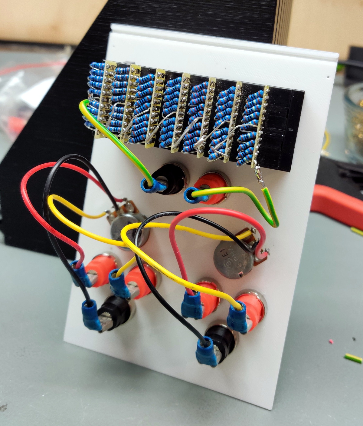
So what’s included? Naturally [Chrismettal] has created a power supply module, in both variable and fixed flavors. But there’s also a module for a resistor substitution, a component tester, and even a digital storage oscilloscope. You can mix and match the modules suit your needs, and if you want to create entirely new ones, the FreeCAD sources are available to get you started.
We’ve seen low-cost power supply modules before, and naturally we’re no strangers to cheap DSO kits. But this project wraps those devices and gadgets up into a form factor that anyone would be happy to have on their bench. We’re exceptionally interested in seeing new modules developed for the EleLab_v2, and doubt this is the last time you’ll see this impressive project grace these pages.
[Thanks to BrunoC for the tip.]


Takes me way back, did something like this in a foolscap (bigger than A4) plan portable format all cobbled together before I knew much about production engineering or efficiency in my mid teens. Haven’t taken it out of the store/box repository for over 30 years, yikes :sigh:
Nice looking unit with an art deco feel to it almost like an updated early series USA tv series Mission Impossible tech spy angle. Last few years I’ve been musing on design for an A3 or A2 sized case maybe 15cm or so thick with the key instruments and power supply including compact multi use tools and storage space for parts, with of course battery pack etc
Thanks for post, looking forward to comments, cheers :-)
I’m getting that warm fuzzy Heathkit feeling :-)
I’ve had this problem for the last few years, now I have a collection of HK. Gear. Steve.
I’ve got this clipboard case aka storage clipboard, that I am always ruminating about turning into a mobile hackstation. But I keep changing my mind about what I want in it. I don’t know if I’ll end up buying 5 of them, or making a bunch of swappable modules or something.
I bought a “Posse Clip” and used it all through college – and ever since! Nearly identical to this. I never thought of using it as an enclosure for portable gear but you definitely give me some ides. https://www.amazon.com/Blue-Summit-Supplies-Clipboard-Compartments/dp/B07B9N1RH8/ref=sr_1_23_sspa?dchild=1&keywords=Posse+Box&qid=1590438615&sr=8-23-spons&psc=1&spLa=ZW5jcnlwdGVkUXVhbGlmaWVyPUEyMUw2UlJGWklCTjQzJmVuY3J5cHRlZElkPUEwNDcwMjk3NldDV0RGSE80VEsmZW5jcnlwdGVkQWRJZD1BMDg2ODQ3MDFFMEJHUlhGWDU4Vzkmd2lkZ2V0TmFtZT1zcF9tdGYmYWN0aW9uPWNsaWNrUmVkaXJlY3QmZG9Ob3RMb2dDbGljaz10cnVl
That’s fairly cheap for an all aluminum one too. Mine is plastic, so half my head scratching is used up on figuring out how to brace it better. Those should be fine with a few cutouts etc. Probably can’t do better for a shallow metal case to use for a wall mount something either.
I don’t know how far this actually opens up, but if it opens far enough, I could see this possibly service a fully closable, or maybe even a dual use hackstation. I suppose that a few very common features could be mounted to the outside, like a DMM, a PSU, etc… The basics… The jacks could be on the front edge of the main body. Thing is, if you mount most of the displays between the clipboard and middle divider, then you could possibly open this like a laptop, and have DMMs, a DSO, power supplies, etc mounted int he thinner top section. You might need to separate some LCD modules and run them over some ribbon cables or something.
You’d have to add another panel to the lower section to close it off (since you’d be using the middle section with the top), but maybe you could fit in some extra features down in the lower section. I’ve seen low profile rotary decimal switches that could be used as part of a resistor or capacitor substitution box. You could have additional adjustable power supplies… I mean the limit is literally the imagination, and what you can make fit.
If you make the lower panel with a bend in it, you could theoretically have bulkier electronics, even batteries, in the thicker section, and mount knobs on a custom board situated in the thinner section, to accommodate closing the unit, while having room for knobs and such.
Just a little thinking out loud.
Love it
reminds me of a “control panel” we made in primary school as part of the space theme. Probably something to do with the first shuttle launch
Oh wow, it me! Thanks for the post! I am in fact working on more modules, just finishing on an ATX infeed instead of the SFX as more people have old ATX supplies laying around. While i will be making more modules i also hope to see the community spin their own. I am happy to see if people will build their own EleLab_v2, please share some pictures and just general feedback if you do!
How about a module with a TS12 soldering iron? That’d really finish it :)
Sorry, that’s supposed to be T12. They come in modules like the DSP3005 at the usual chinese sources.
I had an idea to package various test instruments int the same housing used for cheap (but larger than usual) DMMs. Using a common colour LCD and rotary selector/push you could design AF, RF, variable PSU, even a small ‘scope into handheld sized units.
The design shown here is ideal for schools and colleges though.
Really nice !
I need one.
Really nice !!
I’m doing one. I’ll had a waveform generator, voltage/current monitoring , RF dongle, temperature sensors, and an USB hub hiding UART/USB , I2C analyser..
The panel looks good, i will think about something like this.
I’m so being reminded I have all the parts for the SMD resistor decade box project… in a zip lock bag waiting for me to stop neglecting. :-|) Still waiting on the other SH72’s and tips for the “tweezer” build and the TS100 tip mod.
Neat design and build!
The decade box is overly complicated to get you *one* resistor and taking up space/lab budget. It might have been useful back in the old Wheatstone bridge days for measuring things. It is not a scaleable/practical for building a project. You are much better off with a multimeter and half a dozen of potentiometers for tinkering.
Speak for yourself. I use mine all the time to quickly dial in a resistance when I’m prototyping. Using an arrangement of pots and a multimeter to read their values sounds a lot more complex and finicky to me.
The half a dozen of pots can be used as half a dozen resistors. It doesn’t take that much time for a multimeter. How many decade boxes do you use in a non-trivial project?
If I know the exact value of the resistors which I normally do with calculation/simulation, I would just use the fixed values one.
How about an Arduino Nano and a half dozen digital pots and a readout? Microchip has SPI device with 256 steps. https://www.mouser.com/datasheet/2/268/22060a-53835.pdf TI has IIC with 256 http://www.ti.com/data-converters/digital-potentiometer/products.html
Watch out for their input/output ranges as they can clip and do all kinds of weird things when that exceeded.
Love this idea!
Side-tip: Always twist/braid your Power+Ground pairs of wires together, leading from the Bus100 PCB to wherever the destination sockets/boards are located. It’s an easy noise-mitigation trick I learned 30+ years ago (ack!) from my (VE3SLG) Amateur Radio Elmers which served me well on thru my E.Eng labs and professional years since.
This is way cool and solves a problem I have had moving my electronics from the workshop to the office.
Thanks for sharing this.
Beautiful! 😍
Maybe add a few labels? I’d have trouble remembering what plug is what after a long vacation.
I think it could benefit with a backplane to carry signals/power from one module to the next.
oK, now that I’ve followed the link, I see it does use a “bus” to connect modules.
I wish the HaD author would have mentioned that…
A very neat design, well done! But how long does it take to print one of the 100mm housings?
The basic idea is not far away from the classic 19″ rack system. Maybe it would be possible to build something similar with dimensions based on a 3HE front plate and use a laser cutter to build the housings? I am getting new project ideas here… Thank you for the inspiration!
I made a smaller version a while back, called the “Tiny e-Lab”
You can check it out on thingiverse: https://www.thingiverse.com/thing:2999383