The goal of Printed It is to showcase creations that truly embrace the possibilities offered by desktop 3D printing. The most obvious examples are designs that can be printed quickly and cheaply enough that they’re a valid alternative to commercially available products. But as previous entries into the series have shown, there are also technical considerations. Is it simply a duplicate of something that could be produced via traditional means, or does the design really benefit from the unique nature of 3D printing?
A perfect example is the Print-in-Place PCB Holder/Gripper created by SunShine. This design is able to hold onto PCBs (or really, whatever you wish) without any additional components. Just pull it off the bed, and put it to work. While having to add a rubber band or generic spring would hardly be an inconvenience, there’s always something to be said for a design that’s truly 100% printable.
 The secret is the dual flat spiral springs integrated into the device’s jaws. While most of the common thermoplastics used in desktop 3D printing are relatively stiff, the springs have been designed in such a way that they can be printed in standard PLA. The backside of the jaws have teeth that mesh together, so the energy of the springs is combined to provide a clamping force. Serrations have been added to the jaws to catch the edge of the PCB and help stabilize it.
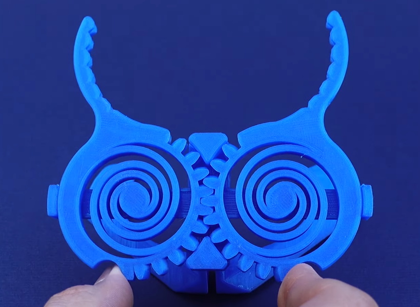
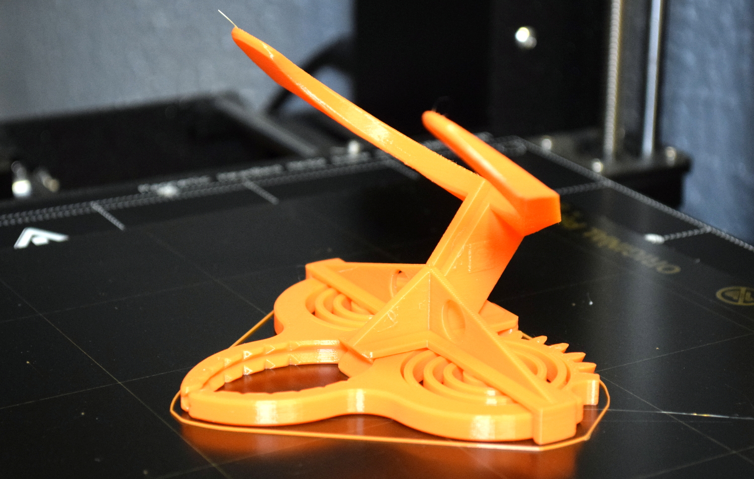
Visually, it’s certainly striking. The design largely eschews right angles, giving it an almost biological appearance. Many have compared it to the head of a mantis, or perhaps some piece of alien technology.
There’s no question that the design leverages the strengths of 3D printing either; there’s no other way to produce its intricate interlocking components, especially without the use of any sort of fasteners. In short, this design is an ideal candidate for Printed It. But there’s still one question to answer: does it actually work?
Choose Wisely
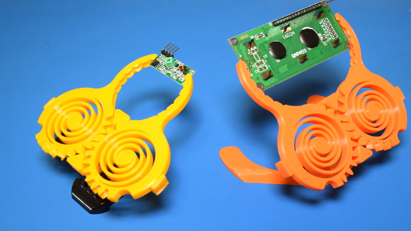
The PCB Gripper comes in two distinct variants, so before you warm up the extruder you’ll need to make a pretty important decision. One version has an integrated stand, which has been designed in such a way that it will hold the PCB at a roughly 45 degree angle relative to the work surface. There’s no way to adjust the stand (short of heating the plastic and bending it), but it’s a fairly comfortable angle so you probably won’t feel the need to.
 The other version forgoes the integrated stand in favor of a GoPro style mount. There’s a large selection of both printable and commercial mounts and stands that use this style of attachment, which makes this version of the Gripper far more versatile. Of course, you’ll actually need to have those accessories. Without a mount, this version of the Gripper can’t even stand up on its own.
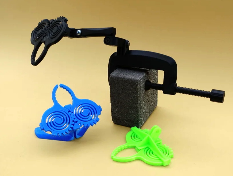
So which one should you print? If you’re just looking to play around with the mechanism and have a useful little gadget on your bench, then the integrated stand version is probably the best bet. The downside is that it takes quite a bit longer to print, but at least it will be fully independent when it’s done. On the other hand, if you want to actually put the Gripper to work and are willing to buy or print an articulated mount for it, the GoPro version is clearly the superior option.
Pushing the Envelope
These sort of print-in-place designs are notoriously unforgiving when it comes to poorly tuned printers, but SunShine has done his best to make sure as many people as possible can run this design off with acceptable results. All of the tolerances are a healthy 0.3 mm, so even entry-level printers shouldn’t have too rough of a time of it.
Which is not to say the design is without challenge. For the mechanism to work, it’s crucial that all support material generation be turned off in your slicer settings. You’ll need to have faith in your printer to navigate some fairly extreme overhangs and bridges, even if they might seem insurmountable at first glance. Bed adhesion is also crucial, since even a slight warping is likely to render the final mechanism inoperable.
 If you decide to go with the integrated stand version, you’ll really be in for a treat. To make sure nobody accidentally gummed up their spring mechanism, SunShine had to design the angled base in such a way that it would print properly even with supports off. The easier route probably would have been to just design a base that you could just attach to the GoPro mount version of the Gripper, but where’s the challenge in that?
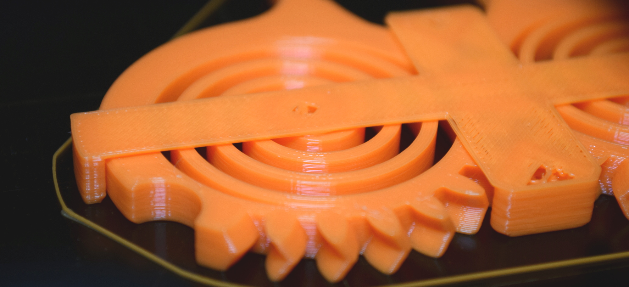
Instead, he uses what might be one of the most extreme overhangs I’ve ever seen on a 3D printed design. At approximately 70 degrees, it’s far beyond the normal “safe” range for an unsupported overhang, but incredibly it seems to work out pretty well. It’s definitely not perfect, and on close inspection you can see some irregularities in the surface, but for a practical component like this it’s more than acceptable.
Time and Materials
At 0.2 mm layer height, the integrated stand version of the PCB Gripper finished in around 4.5 hours and the GoPro version in less than 3. Naturally, you’re mileage may vary, but that should give you an idea of what to expect. Printing at a higher resolution might clean up the bottom surface of the stand overhang a bit, but personally I don’t think it would be worth the extra time.
SunShine recommends the design get printed in standard PLA, but I also ran off a version in PETG. The glass transition temperature of PETG is considerably higher than PLA, which I hoped would help prevent any issues from extended soldering sessions. PETG is also a bit more flexible, which seemed like it would be a benefit.
But as it so happens, the more flexible material was actually a mistake. While the Gripper printed fine, the springs are obviously much weaker than their PLA counterparts. ABS may give you a good balance between flexibility and temperature resistance, but its temperamental nature could make such an intricate print difficult.
Putting on the Pressure
To be clear, I think this is a phenomenal design and SunShine deserves nothing but praise for what he’s accomplished here. This may well become one of those “must have” prints that people will do just to see how the mechanism works. If you’re looking for a good example of the sort of non-traditional designs that are made possible by affordable home 3D printing, this is as good as any.
As a practical tool though, there are some pretty glaring issues. Even when printed in the relatively stiff PLA, the springs just don’t have a lot of strength. This is especially true with smaller boards, as the springs don’t seem like they wind back far enough to really exert any force on the jaws. It definitely works better with larger PCBs, but those introduce a different problem. After using it just a few times with larger boards in the jaws, the springs have weakened to the point that they no longer close fully on their own.
But even when you’ve found a PCB of the right size, the mechanism itself still has a lot of play. It doesn’t take much pressure from a soldering iron or probe to push the jaws out of alignment and rock the board back. Those with a gentler touch might feel differently, but I found this to be a show stopper personally.
In the end, I think this is a great design to show off what your new 3D printer can do. But I wouldn’t count on doing much soldering with it. If you just want to print something that will hold a PCB still while you work on it, a more traditional design would be a much better bet. If you need something that looks really cool to hold boards at your table during the local Maker Faire, this one’s for you.


I was feeling deja vuey because of https://hackaday.com/2020/06/17/print-in-place-helping-hand-grabs-a-hold-of-your-pcb/
But then I realised the goal of this new “Printed it” column is to review such items and what happens and how good they are when you print them yourself, rather than to say “J Random Hacker did this…” Hopefully this will save us all a lot of duplicated mistakes and hence filament.
Looks like an owl to me.
I saw it as a bra.
I guess it does look a bit like a sports bra.
I put this article in Google Translate and here is what comes out:
“Buy a PanaVice, you won’t regret it”
Lol.
Im actually thinking this would be amazing in metal.
Instead of normal centerpiece, put a square hole in the middle of the spring, and mill that through. Use that to bolt down to a jig that fits the square. Cut out the perimeter of the gear, and mill the spring area out with a small, say 1/8″ endmill, almost all the way through- but leave like 0.01″ on the floor of the part. Run a chamfer tool around all cut edges. The radii left in corners of spring terminus points inside would give it strength to keep the spring from breaking from fatigue as quickly.
Flip it over, 180 degrees, and bolt down on the jig square. Write another program for chamfer tool that is the mirror image of the first side, and if the jig didn’t move, you can chamfer the outside of the part, then one half of the spring inside fully to remove the 0.01″ skin, then work from either one side, outter edge, or inner edge, chamfer on the opposite skin side to free the spring without it bouncing while cutting, and have a fully chamfered ready to go gear.
Youd have to make a new type of backpiece to lock the gears together, but thats just a bar with 2 oriented square posts in alignment.
Custom arms with insertable bits for different style grippers 3d printed with ninjaflex would grip well, and metal springs would need to be adjusted for thickness for given metal for right tension.
I used to cut parts out of large sheets of plastics with a vaccum table in the same way- leave a 0.005-0.03″ skin on bottom, put in a jig and mill skin off. It works!
Metal is good for high temperature stuff and stiffness which is perfect fit for this.
Don’t use plastic when you have job for metal.
Yeah- but plastic was made for stuff like this.
Its easy to prototype quick with plastic, and easier for most people to print stuff. Metal is just the next step, its all making though.
design could be tweaked with 4 spring attachment points 90 degrees apart- with new spiral- that would give stiffness against bending but still make it work correctly.
i Printed one of these a couple weeks ago for the novelty. It printed fine and worls surprisingly well. I am amazed at the creativity of people.
If you feel like the springs aren’t strong enough you can advance one or both of the gears a tooth and pretension it. All you need to do is pull it upward from the side opposite where they mesh, then you can realign them and add more tension. Also works with pip boxes that have lost their spring.