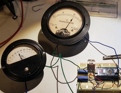
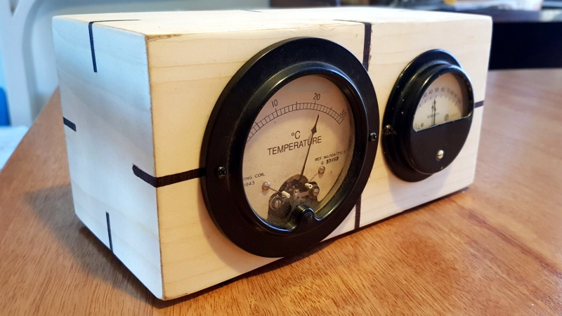
It’s always good to see old hardware saved from the junk pile, especially when the end result is as impressive as this analog gauge weather display put together by [Build Comics]. It ended up being a truly multidisciplinary project, combing not only restoration work and modern microcontroller trickery, but a dash of woodworking for good measure.
 Naturally, the gauges themselves are the real stars of the show. They started out with rusted internals and broken glass, but parts from a sacrificial donor and some TLC from [Build Comics] got them back in working order. We especially like the effort that was put into making the scale markings look authentic, with scans of the originals modified in GIMP to indicate temperature and humidity while retaining the period appropriate details.
To drive the 1940s era indicators, [Build Comics] is using an Arduino Nano and a DHT22 sensor that can detect temperature and humidity. A couple of trimmer pots are included for fine tuning the gauges, and everything is mounted to a small scrap of perfboard hidden inside of the custom-made pine enclosure.
This is hardly the first time we’ve seen analog gauges hooked up to modern electronics, but most of the projects are just that: modern. While the end look might be somewhat polarizing, we think maintaining the hardware’s classic style was the right call.


Pots to tune (or calibrate) the meters?
Meters are actually the reference to which you calibrate.
The magic figure is Full Scale Deflection (FSD) current. Often in a 1,5 sequence like 50uA 100uA 500uA 1mA.
Knowing this figure and the coil DC resistance will allow you to calculate the FSD voltage and series resistors for volt meters and shunt resistances for current meters.
I inherited a few of these meters from my father but haven’t done much with them. Most of them measure very low currents and aren’t much use to me for that, but making them into a weather station sounds fun. Surprisingly, I haven’t taken any of them apart, but if I can manage to do that and replace the dial plates as was done here, that opens up a lot of possibilities.
Internally most meters are very low current meters, they use a shunt…
https://www.electronics-tutorials.com/test-equip/meter-shunt.htm
FSD can indeed be used to have a fixed resistor. Do note however that with PWM and slightly varying voltage levels, and finding the correct resistor value a trimpot is often faster.
This works only for moving coil meters. Most old meters I took apart untill now that have high current measurements do so using moving iron: https://electrical-engineering-portal.com/moving-iron-instruments-voltmeter-and-ammeter.
Moving iron meters are an entire different beast. They are not linear and require much more current, and often a different a different coil to make them usefull. However, I feature a build comic on how to conquer those as well.
Shunts for most moving coil meters are generally not inside the meter, but externally. You will often find large normal resistors on the back of small gauges, but wires or sheet shunts for larger meters.
I also have seen wire wound spools and plates acting as resistors for both moving coil and moving iron meters.
If you plan to make your first gauge display, pick a moving coil one as these are easier to deal with (assuming they are in a working condition. Fixing them up can be more fiddly then a moving iron one). Just my tip ;-).