If you’re a human or other animal with two ears, you’ll probably find great utility in your ability to identify the direction of sounds in the world around you. Of course, this is really just a minimal starting point for such abilities. When [John Duffy] set out to build his acoustic camera, he chose to use ninety-six microphones to get the job done.
The acoustic camera works by having an array of microphones laid out in a prescribed grid. By measuring the timing and phase differences of signals appearing at each microphone, it’s possible to determine the location of sound sources in front of the array. The more microphones, the better the data.
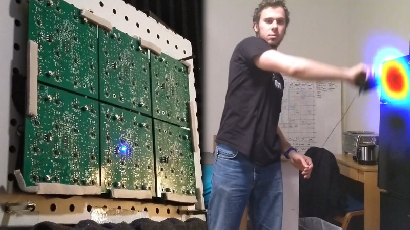
[John] goes into detail as to how the project was achieved on the project blog. Outlining such struggles as assembly issues, he also shares information about how to effectively debug the array, and just how to effectively work with so many microphones at once. Particularly impressive is the video of [John] using the device to track a sound to its source. This technology has potential applications in industry for determining the location of compressed air leaks, for example.
Overall, it’s a university research project done right, with a great writeup of the final results. [John]’s project would serve well as a jumping off point for anyone trying to build something similar. Phased array techniques work in RF, too, as this MIT project demonstrates. Video after the break.


very nice, love it.
Thanks!
Mieto approves
https://im.mtv.fi/image/5249274/portrait/368/614/afabab4bec6df0202ed004f34e28fec8/kb/juha-mieto.jpg
If portable enough it may assist Deaf persons in identifying sound types and sources too,
I’ve love to buy/borrow/rent something like this for tracking down those hard to find bike squeaks.
I wonder how well would it work with the engine running. I guess the noise would jam it completely. But maybe you can setup bandpass filter for that exact squeak you are looking for.
Bicycles don’t typically have engines.
I was asuming “bike” refers to “motorbike” as pedal powered bicycle is simple enough to be debuged without such complex approach.
You’d think so, but you would be wrong.
There are a nunber of commercial devices that do basically the same thing that you probably could buy/rent. They cost a pretty penny though, guess it depends on just how badly you want to fix squeaks :)
At first was like, why? Then I thought of what applications this could be used for, and the world opened up!
Possible uses:
For the deaf, if these were integrated into glasses or something, it could tell them where sound is coming from.
For the military, find out where artillery is coming from.
For finding out where sounds are in a quiet room to eliminate distractions or just any room if theres a squeaking pipe or something.
Searching for people in earthquake zones.
Could be used with AI to identify the sounds onscreen with text and arrows overlaid. Eg: “Cat” if a cat meows nearby.
I have more but that’ll do for now :)
Saw something at CES this year that jumped to mind when i saw this. Bosch system for acousically mapping the ISS for equipment monitoring.
https://www.bosch.com/stories/acoustic-sensors/
Nice concept and execution.
It does make me wonder what is the cross over point between something like this with many many audio receptors and something with fewer audio receptors but with ear shapes to help with localisation.
haha, next project: array of 3d printed ears :)
Microphones are such underrated sensors. Super cheap and sensitive. An entry level microcontroller can sample it fast enough to do some usefull DSP. Add an acoustic filter, laser, some servos and nuke those mosquitoes.
Well, at least it will detect the males.
This is really great stuff. As someone who lost hearing in one ear a few years ago and as a result can’t locate the source of sounds, I really like the idea of something that can show me who is talking in a meeting (or what direction the ambulance siren is coming from!). Very cool.
Thanks!
And sorry to hear that (no pun intended)!
One thing I found from simulations was that if resolution isnt a big concern, just general direction, sparse or uneven array geometries actually work pretty well over a wide band. Now I’m interested to see if something like a small array hidden on the sides and rims of pair of glasses could do at least basic direction finding, Ill look into it!
Don’t need 96 mics to do that. What about actual reflective imaging? Narrow band acoustic point source, maybe 20 kHz. Every mic hears sum amplitude/phase of reflection from arbitrary object. Compute the surface.
thats what i thought!
Looks already pretty good. But the resolution will need some improvements to be clear enough for real-world applications. There was a successful Kickstarter campaign to the same technology acoustic camera https://www.kickstarter.com/projects/351002836/the-first-handheld-sound-camera-for-everyone
I just saw this ad for the first time last week.
And… I forgot the link
https://www.youtube.com/watch?v=7Wx9B_0n1co
Cool, it looks like a phased array is used to capture the sound, and possibly filter for the needed frequency(s).
Congratulations to you and your team John. Fantastic & interesting concept and impressive implementation.
Thanks!
https://youtu.be/BH63ixKTLts
Well done!!
What’s even more interesting in the (short) video finding the sound is that the “random signal” scatter shown on the screen might be reflections or some other artifact that may be of interest, particularly for those who are designing acoustic devices and architectural spaces.
If you can locate the source, you can then follow the reflections, at least to a degree.
Thanks!
If you poke around on the channel (for some reason the yt link wont post), there is a video showing reflections as well, which this was able to see. The artifacts in the video are from the automatic gain control though, which is done on a frame-by-frame basis, it boosts the “gain” until at least one pixel is fully saturated. So, these are just random noise being amplified, actual reflections are more stable.
I did end up extending this a bit based on that idea though! I had a speaker play a barker coded pulse, then used the reflections of that off of things in front of it to do spatial (3D) mapping (though thats got a ways to go before it works well).
Aren’t acoustic cameras already commercially available?
https://www.acoustic-camera.com for example, and B&K sell one.
I have even used one, to locate where the noise in an engine bay comes from (working as a vehicle NVH engineer).
So it seems that if this is a research project it must be adding something novel to the field?
So a lot of the specifications for this were derived from existing imagers (mainly the fluke one), but this was a senior design project, so we didnt need to do anything particularly novel for the project to be “successful” as far as the class was concerned.
That said, I picked this out as a project because the hardware would be sufficient for a senior design project (and, more importantly, paid for by the school!), and then I could mess around with the signal processing/phased array math afterward, thats what I was really interested in. So, the more novel stuff Ive been working on since then has been more in adding the ability to do 3D imaging based on reflections, though I havent had much time since May to work on this.
Also the hardware cost is pretty drastically different, those imagers generally cost north of a couple thousand, this cost just a few hundred.
I think that you are out by at least an order of magnitude in your estimate of what that special greeny-blue colour adds to the cost of a Bruel and Kjaer instrument. :-)
I work for a company with assets of $250 billion and we still rent one by the week when we want it.
Agree with Andy… you can likely add at *least* two zeros to what you ended up spending on your if you wanted to buy a commercial one. Hell, even renting a commercial one for a week would tack an extra zero onto the cost of yours!
Admittedly the big cost is not the hardware, but the time spent writing the software. Are you going to release yours (have you already)?
I don’t doubt the higher end ones can get to “if you have to ask you cant afford it” range :) but I do think some of the lower-end ones can get down below the $10k mark, and theres a fluke one around 20, thats around the capability range we were targeting (though admittedly with a vastly less convenient ui).
The software is posted on the .io page, though its not particularly user-friendly. Currently theres a C network driver to capture data from the fpga and save it in a text format, and a matlab script to generate images. I dont really have plans to clean it up and make a nice official release right now, but may eventually.
Any idea how much the Mikado costs, if you’re allowed to say?
Very interesting! Do you think it would work at ultrasonic frequencies?
Most of the arrays I’ve seen are specifically for ultrasonic, this one I made specifically for normal “human range” frequencies. The array geometry (spacing between elements) really dictates what frequencies are useful. This can easily pick up ultrasonic, but will have all sorts of artifacts and other issues if you go above about 10~15KHz, as your wavelength is smaller than the mic spacing. Designing for 20+ khz probably wouldnt be very different, it would just have the mics placed closer together, so you would either lose low-frequency performance (gain) since the array would be physically smaller, or, need more elements. Above about 35khz the spacing would probably get problematic, the mics would be too big to fit, youd have to get smaller mics or do a sparse array.
Thanks! I work with laboratory mice in my day job, so I was wondering whether those array mics would work for tracking their position by their ultrasonic vocalizations. Those are somewhere in the range of 75 kHz, so I guess that is going to be tricky without radically redesigning the array?
Anyways, super interesting to see what you can do with a lot of cheap sensors and tons of computing power :)
It would depend on exactly what the vocalizations are like, if they’re ‘pulse compressed’ at all, then it may be possible. You could probably set a couple of panels up around the enclosure, do 3D processing like you would for reflections and just throw out any readings outside the mouse chamber (hall of mice? mouse arena? 🙂 ). Or if the vocalizations have multiple components at different frequencies (like say, peaks at 70k,75k,80kHz), then you *may* be able to get away with the same kind of spacing and processing and just rely on product-of-images (described in the video) to cancel out artifacts. Either way you’d *probably* want to do 3D processing instead of linear tdoa, once you start getting close to the array, the far-field simplifications stop working. Thats pretty simple geometry though, the core concept is still thr same
If you’re still looking for solutions visualizing sound sources ranging up to 75kHz – 100kHz you should check out our website Sorama.eu.
I’ve wanted to make one of these before. There was actually one on Hackaday before. It’s a shame the tags don’t always reveal similar projects:
https://hackaday.com/2016/07/01/1024-pixel-sound-camera-treats-eyes-to-real-time-audio/
Nicely explained as well. I was aware of the delayed sum method, but the frequency domain method was new to me. Given that this was an 10 minute video and I feel like I could implement it now, that’s a pretty solid explanation.
Thanks!
Before radar, aircraft were detected with sound, https://en.wikipedia.org/wiki/Acoustic_location I wonder if, with stealth aircraft (subsonic of course) this could be used to track them in flight?
The array needs to be physically larger, I’m picturing a wall sized array (or even multiple walls). That way by adjusting the phases of each individual microphone you could have an audio zoom lens to listen to individual conversations in a large crowd. I bet the NSA, CIA and FBI have already have already implemented that with rewind.
Thinking just add like Shannon noted some sort of “ear” micro dish or trough with minimalist actuator designed to a patterned optimal sweep area rate to create a passive synthetic aperture phased array. I have to read into the blog next. Very neat to read about, great video detailing and thanks for sharing too!
https://www.head-acoustics.com/eng/nvh_head-visor-flex.htm
If B&K ist mentionend, HEAD Acoustics should be mentionend to.
Nice project.
now Ghost Hunters has another item they can use to make marginal TV.
Could this be done in reverse with an array of speakers to make a sound projector?
Yes, absolutely. I have interacted with a demo system that uses focussed ultrasound to give touch feedback to a virtual button panel floating in space.
There is wave field synthesis https://en.wikipedia.org/wiki/Wave_field_synthesis
Could you use the system to locate noise disturbances in a suburb? I have been trying to locate a serial noise polluter/s in our suburb for a few years without much luck. The problem is that the low frequency music travels far (kilometers) and to the human ear is virtually directionless. Or are there other approaches that could work better for this application?
Could one use this to visualize where Dolby Atmos objects (not the speakers) are in an actual space from the listener’s position versus where they were placed in the virtual space? If not, how might one want to try to approach that?