It doesn’t matter whether you know it as a railway, a railroad, a chemin de fer, or a 铁路, it’s a fair certainty that the trains near where you live are most likely to be powered either by diesel or electric locomotives. Over the years from the first horse-drawn tramways to the present day there haven’t been many other ways to power a train, and since steam locomotives are largely the preserve of museums in the 21st century, those two remain as the only two games in town.
But step back to the dawn of the railway age, and it was an entirely different matter. Think of those early-19th-century railway engineer-barons as the Elon Musks and Jeff Bezos’ of their day, and instead of space and hyperloop startups their playground was rail transport. Just as some wild and crazy ideas are spoken about in the world of tech startups today, so it was with the early railways. One of the best-known of these even made it to some real railways, I’m speaking of course about the atmospheric railway.
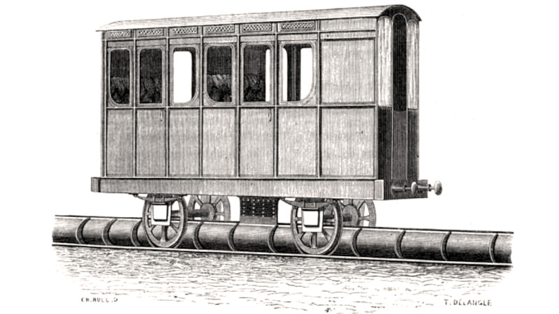
These trains were propelled not by a locomotive, but by air pressure pushing against a piston in a partially evacuated tube between the tracks.
This Railway Sucks
Looking at the steam locomotives of the 20th century that form the bulk of those in preservation it seems curious that such a system might find favour when steam did such a good job of pulling trains. But the locomotives of the 1830s and 1840s at the dawn of the railway era did not have either the power or the traction of their later stablemates, and when faced with any significant gradient were often unable to tackle it.
The atmospheric system promised to solve this problem by replacing the relatively small mobile steam engine on the locomotive with a much larger one by the tracks, and removing the limited adhesion between the single driving wheels of those early locomotives from the equation entirely. A train would be simply pulled up the slope by the invisible hand of atmospheric pressure, something which seemed attractive to early railway companies not keen on the idea of digging expensive cuttings and tunnels to replace the inclines.
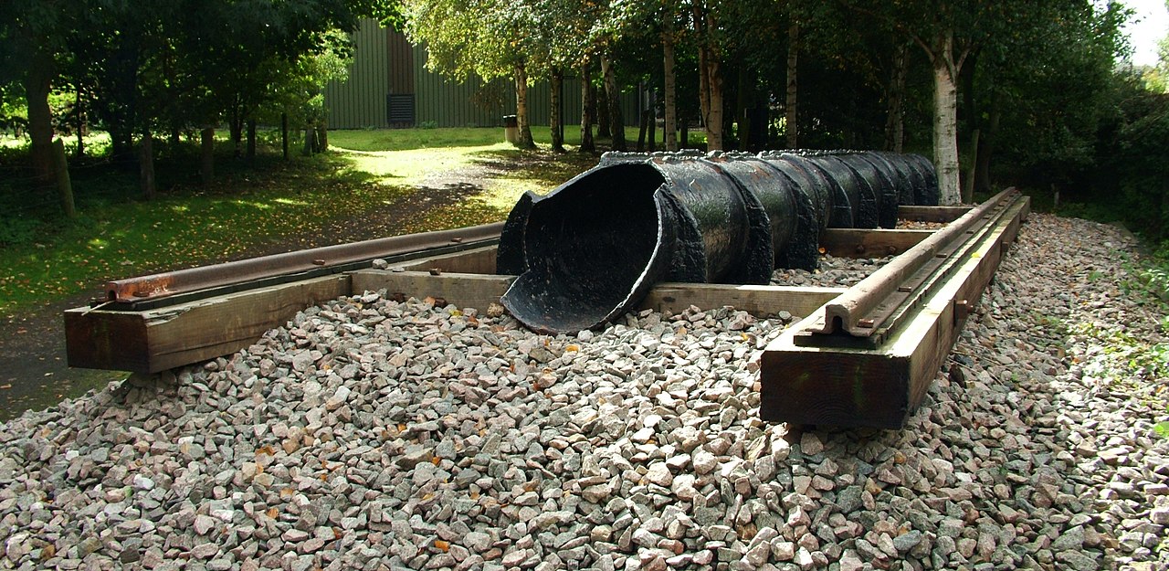
The atmospheric tube was made of cast-iron sections bolted together and mounted between the rails. Along the top of the tube was a slot for the piston rod to pass through, fitted with thick greased leather flaps designed to separate as the piston passed but to provide a vacuum seal at other times. It was successful enough to be taken up by several railway lines of the day, but why don’t we hear about it today? The answer is one with several layers, and is best answered by looking at those lines which proceeded as far as putting the system into practice.
Not All Atmospheric Railways Were A Failure
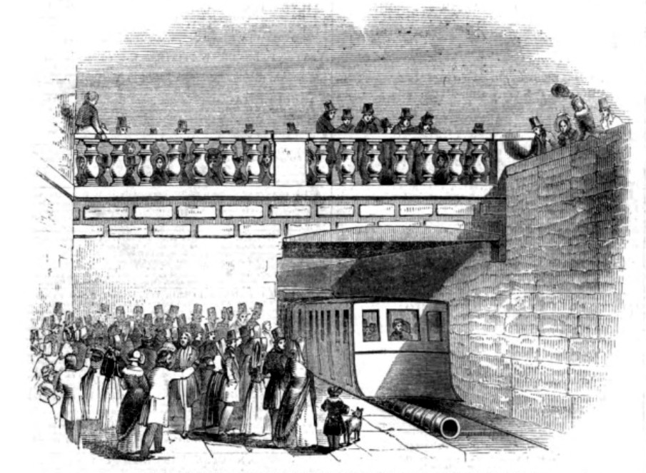
The first successful atmospheric railway was in Ireland, connecting the port of Kingstown (now Dún Laoghaire) near Dublin to the settlement of Dalkey, a distance of 1.74 miles. It opened in 1843 as an extension to the existing Dublin and Kingstown railway, and continued in operation until the mid 1850s when its traction was replaced by more conventional steam locomotives. Its success provided the inspiration for atmospheric traction in Paris on the railway from Paris to St Germain, the last 1.5km section of which was to have a gradient too steep for a locomotive. it opened in 1847 and like the Dalkey line continued in use until the advent of suitable steam traction which replaced it in 1860.
Both the previous two lines were very short sections in places that would soon become part of the populated suburbs of their cities, but those which followed attempted to bring atmospheric traction to longer distance travel. The London and Croydon railway was an 8.75 mile line whose local traffic shared tracks with express trains from another company, and it was proposed that another track be laid alongside the main line for these local trains, which would use atmospheric power. The first section opened in 1846 and showed promise in tests, but suffered a series of catastrophic pumping engine failures soon afterwards which caused its abandonment in 1847 in favour of steam power.
Probably the most well-known and most ambitious of the atmospheric railways is the South Devon Railway, with the famous Isambard Kingdom Brunel as its engineer and part of his Great Western empire. It was planned that the entire 52 miles of the line between Exeter and Plymouth would be using the atmospheric system, but the first section to be completed in 1847 was that from Exeter to Teignmouth, a distance of about 13 miles. It was plagued by a series of problems like seals that froze shut in winter and dried out in summer, and by inadequate power from the series of pumpin engines set up beside the line. It was abandoned in favour of steam traction in 1848, and remains part of the main line to the West Country today. It’s this railway which defines the public history of atmospheric traction as one of the great Brunel’s failures, casting its successes in France and Ireland into the shade.
The atmospheric railways then are a mere footnote in engineering history where they live alongside such other interesting ideas as the maglev. It’s obvious that it’s an idea with potential and it’s certain that a modern version using the same pipes with perhaps a Neoprene or a silicone seal could be considerably more successful. But perhaps its time simply came and went, while it’s a good idea it had the simple misfortune to be not as good as a locomotive once locomotive technology was sufficiently developed. And that fate is something that’s happened to far greater inventions than an iron tube with a strip of leather along its top.


Don’t forget the counterbalance trolley on Queen Anne hill in Seattle.
Funicular?
https://en.wikipedia.org/wiki/Funicular
You can’t spell Funicular without “Fun”, or “Icular” but that’s beside the point.
There’s an interesting two-car trolley, the “Ascensor da Glória”, in Lisbon, Portugal. The two cars are attached to each other via a long cable which goes around a pulley at the top of the 22 degree slope. Originally, the cars were powered by a water counterbalancing system- the upper car had a tank which would be filled from a reservoir. The weight of the water was enough to pull the lower car up the incline as the heavier car came down. When the heavier car reached the bottom it drained it’s tank, the upper car would fill its tank, and the cycle repeated. It later progressed through a steam powered cycle, and is now electric.
the best part is the fact that they used BEEF TALLOW as the grease for the leather flaps, which meant it attracted rats like a magnet. it’s probably an unsubstantiated rumor from the time, but allegedly this meant rats getting sucked into the vacuum tube at times, and subsequently getting eviscerated into rat goo.
I’d say beef tallow probably attracted rats even better than a magnet would
I wonder if the rats made a ‘poof’ on the way through?
Rat goo. New term for my term toolbox.
“modern version using the same pipes with perhaps a Neoprene or a silicone seal could be considerably more successful.”
What did/does the US Navy use to seal its catapults on A/C carriers?
The pre-electric catapults are more like a hydraulic ram and used steam and a stroke that is not very long compared to the pace it uses on deck. They move a sheave with a bunch of pulleys and mechanical advantage is traded for length of the cable that pulls the plane. https://www.youtube.com/watch?v=MJAyGKT98RM
The steam catapults use a flexible metal seal that the traveling piston separates and re-seals as it travels. It may not be particularly energy efficient, but they have a lot of energy available. They need the extra energy because if the seals fail while at sea, they still need to be able to launch aircraft. But expending that much power on seals would likely rob an ‘atmospheric train’ of its energy efficiency.
Some videos even show steam escaping the full length of the catapult as the plane leaves, where the seals are leaking just about everywhere, and you can see they continue to provide enough assistance.
I can’t help but to think of the numerous maintenance and efficiency disadvantages compared to DC powered electric trains…
The seal surely must add additional friction. Thereby lower power efficiency.
The seal surely leaks, thereby adding actual power losses.
And then the piston within likely also adds its own friction and its own leakages around it…
And that is before we even look at the air resistance of the pipe itself.
I wouldn’t be surprised if a regular third rail or overhead cable outperforms this solution in all aspects. Be it cost, efficiency, or ease of maintenance.
Pneumatic post on the other hand is something that could see a resurgence, since it is fast, moderately efficient, and able to take a decently sized payload. Not to mention ease of installation within urban environments. (Though, even here a narrow gauge rail way might be more efficient still…)
Would have been better to have a spring-wound train compared to the problems of this idea.
While I agree that an electric train seems better in just about every way, they didn’t enter service until about 1880 while this pneumatic system preceded it by nearly 40 years. And no surprise, its various issues made it obsolete in fairly short order.
The hidden problem they’re trying to solve wasn’t necessarily power distribution so much as it was traction. Each of the atmospherics described above included a section of track with a grade higher than a steel wheeled locomotive was capable of climbing. Steel wheels on steel tracks don’t have enough traction to climb grades of more than about 10%. Other solutions to this problem include cable cars (think of the hills of San Francisco), and cog railways.
Inclines and low friction is a nice combination for not getting anywhere.
One solution is to have more drive wheels. (Some subways for an example has traction on most if not all wheels, giving them rather impressive incline climbing abilities, not to mention acceleration.)
Another is to have a dedicated set of drive wheels that uses a higher friction interface instead, like rubber. Or a cog wheel, though cogs have some issues of their own.
Though, back in these early days of trains, using pneumatic power in this fashion might have been the easy solution.
Regarding using high-friction interfaces, there are several metros worldwide that use rubber-wheeled “trains”, first used in 1956 in the Paris Metro on a line known for steep gradients.
https://en.wikipedia.org/wiki/Rubber-tyred_metro
Seattle’s monorail uses rubber tires.
I remember riding on the rubber-tired Montreal subway system during the summer of 1967. The stink of burning rubber was overpowering.
Another problem that arose a lot was tunnels and people dying from smoke inhalation, particularly if a train broke down, or from the tunnel catching fire if there were a more serious breakdown. (A bunch of people got killed in a train tunnel fire just a few years ago in northern Italy.) Electric and vacuum systems have huge advantages particularly for stuff like subways that never have a chance to vent to atmosphere.
Wouldn’t a wire rope drive be easier, cheaper, and work more reliably?
The folks who make wire rope will tell you that it lasts forever but San Francisco has a huge annual budget for cable replacement.
The cable which does not stop is constantly being grabbed by cars which are stopped to accelerate them. This creates quite a bit of wear.
To be fair, the cable car operator uses a clutch to grab the cable, and skillfully slips it to accelerate gently over time rather than clamping it suddenly and placing a huge shock load on the cable (and sending all his or her passengers flying.) But yeah, they still wear out for all the usual reasons.
They still coat the cables with pine tar as a lubricant because they could not find anything else that had the right combination of lubricating enough while still allowing the car’s grippers to hold without slipping.
Why use something different, if the stuff does the job and doesn’t seem to be especially rare or expensive.
That’s an engineering blog, here is the cross section of the system :
http://www.nicospilt.com/archief/atmospheric-railway-05861.JPG
Thanks, that makes things clearer.
Eyeballing the tube diameter in that drawing, I’m going to guess a bore size of about 1 foot.
6″ x 6″ x pi x 14 psi = almost 1600 lbs
Considerably less in the real world. Is that a useful amount of motive force?
Simplistic analysis: 1600lbs / sin 10 = 9200 lbs. That is the maximum weight that you could accelerate up a 10 degree slope. You’d need to overcome stiction and rolling friction too, but that doesn’t seem completely unreasonable for predominantly wooden cars with 30 passengers.
18000lb for a 5 degree slope.
Also…the design originally called for 12″ diameter pipe on the flats and 15″ on hills, but that was soon changed to 15″ and 22″ respectively, so perhaps the better answer to your question would have been, “Barely!”.
12″ ~ 1600 lbs
15″ ~ 2500 lbs
22″ ~ 5300 lbs.
“Aeromovel”, is likely the most serious modern implementation, moving passengers between terminals in the Porto Alegre airport in brazil.
https://www.youtube.com/watch?v=lQodofJWhVc
Interesting! 👍
For some reasons it reminds me of a low-tec version of a Transrapid, though.
The simpler, the better
I love that this even existed at all.
Humanity never ceases to amaze me when it’s not horrifying me daily.
“Humanity never ceases to amaze me when it’s not horrifying me daily.”
…stealing this one!
Why not just put a huge magnetic slug into a sealed brass tube pump the slug along and have the magnetic field pull the train?
I’m not sure about this, but a quick search reveals that strong enough magnets where not available at the time.
Then even with modern magnets there might be problems with hitting Curie point with friction and other sources of heat in the system.
Here is a modern implementation that does exactly what you describe:
https://www.youtube.com/watch?v=KniP3T_PPB4&feature=emb_logo
If you were building a modern system, why not stick the whole car inside the tube just like a subway/hyperloop?
Oversized pneumatics like the one at the bank window.
That too has been done – https://en.wikipedia.org/wiki/Beach_Pneumatic_Transit
A 1 foot diameter tube can provide over 1500lbs of thrust, depending on the quality of the vacuum. That seems pretty good.
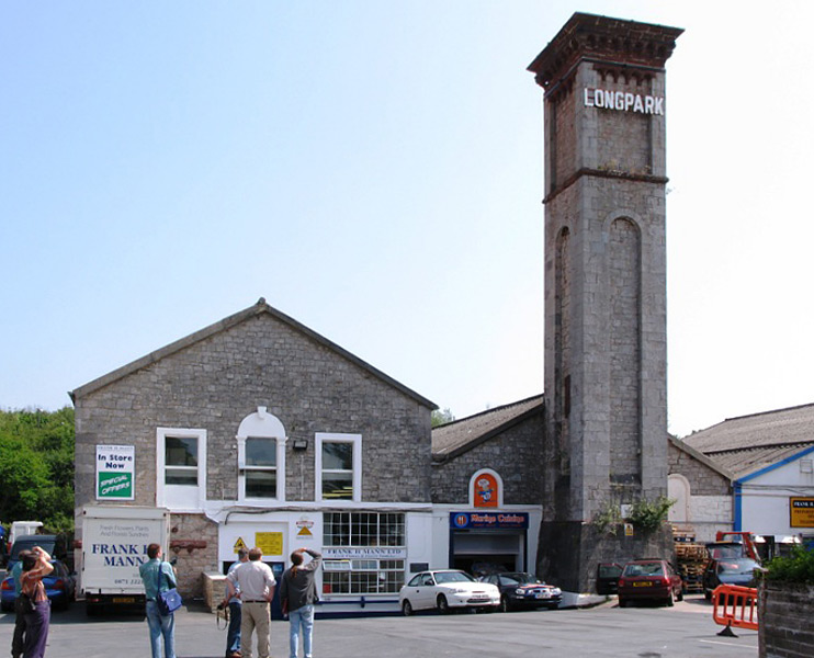
More structures found associated with the atmospheric railway.
https://www.bbc.co.uk/news/uk-england-devon-44099898
For a engineering disaster take on this, with some humor, I’d suggest this episode of the “Well, There’s Your Problem” podcast:
https://www.youtube.com/watch?v=JaRVy31lTlQ
Do note, this podcast about engineering disasters (with slides!) is itself a bit of a disaster… but it’s a bit charming that way.
Steam trains eventually solved the incline problem with a rack and pinion system where a third rail pinion would be engaged by a circular gear. A simple but effective system that is still used today by mountain railways all over the world.
It’s cool to look back at the ‘path not taken’ solutions of the past.
What’s interesting is that according to wikipedia, rack railways were first patented in 1811. So the problem of steep grades was solved and even with an English 20 year patents, the idea of rack railways would have entered the public domain by the time this was invented.
So why pursue this crazy idea that the materials of the day were not up to solving? It looks like piston steam engines were pretty mature tech by that time and should have had reasonable power. The next leap in steam power would be the steam turbine that looks like it was invented about 25 years later.
So I wonder if the atmospheric engine was trying to address passenger comfort, load capacity, speed, or some other issue I can’t think of.
It’s easy to see the appeal, but also easy to see the issues.
Jimbo,
Rats are probably diamagnetic due to the water content.
In backyard https://www.youtube.com/watch?v=KniP3T_PPB4
This video is quite interesting! Covers a model and the history.
This is a fascinating piece of history, from one of my absolutely favourite historical figures, Isambard Kingdom Brunel. It’s one of the few ideas that he implemented that, upon reflection was utterly doomed to fail.
Simple economics would have doomed it if the rats, and other motive power issues, hadn’t. It doesn’t take much thought to realise that the maximum mass that you could pull was limited by atmospheric pressure acting upon the surface area of the pipe, and the ability to pull and hold a vacuum. There was a practical limit to the pipe size. In addition, it just wouldn’t have scaled well. Increasing the network would need new pumping houses to be built, fuelled and maintained, and the pipework maintenance costs were roughly proportional to the network size. Add to that the lack of operational flexibility imposed by the system that would have made it difficult to increase capacity without adding more pump stations, and it’s clear why steam locomotives quickly became the better solution.
Bridges, tunnels, railways, ships. IKB achieved awesome ingenious feats of engineering. It’s always nice for us mortals to see that he wasn’t infallible.
The pumping house pictured had a working scale version of the atmospheric in the 1980’s and they gave demonstrations. I found a photo last week with young me riding on it.
It’s too bad the video “Great!” a [mock/doc]umentary on IKB isn’t availble for free streaming.
You could double or treble the thrust if you push with pressure from one side as well as pulling with a vacuum on the other side.
In theory, yes. You could turn it up to 11 by providing 140psi against a vacuum.
However, practically I don’t think that was feasible. The slot in the pipe was sealed by greased leather flaps. That tells you a lot about the available technology. Vulcanized rubber was only invented about a decade earlier. This was very much the era of animal-fat and animal-hides. The flaps needed to move out of the way of the piston rod, but seal otherwise.
For a vacuum systems you’d want them on the exterior of pipe, lifted outward by the rod, sucked closed by vacuum. For a pressure system you’d want them on the inside of the pipe, depressed inward by the rod, pushed closed by pressure.
I’d think that the vacuum system would be easier to produce as all the work could be done from outside the pipe – Drill and tap mounting holes, and then bolt the flaps on with a long strip of metal as a washer. The holes wouldn’t even need to penetrate to the inside of the pipe.
For a pressure system you’d need the fasteners to be on the inside of the pipe. That makes it significantly more difficult to implement. Avoiding holes that penetrated the pipe might have been practically impossible at the time. Those holes would have then been another potential source of pressure loss, increasing maintenance costs.
Also, pipes are stronger under vacuum than under pressure, especially those with slits. The pipe was exposed to the environment with the slit on the top. Water would have entered the system and caused rust to form, predominantly at the bottom of the pipe due to gravity. Eventually cracks would form at that point. If under pressure that propagation would be accelerated, and I’d imagine that pipe could soon hinge itself open – assuming that the failure mode wasn’t explosively catastrophic. In a vacuum system those cracks wouldn’t undergo the same accelerated propagation. I’m not sure how much the presence of moisture would have been affected by pressure versus vacuum. Certainly water would evaporate quicker in the vacuum, and would constantly be sucked out of the system. A pressure system would condense moisture, requiring drains to remove. I don’t know how those effects would quantify though.
Regardless, air compression was still a nascent science anyway. Compression was commonly used at that time for ventilation and supplying furnace air, which required high volume; but not for energy transfer that would require high pressure. Air-powered jack-hammers weren’t invented until 1857 (first used to dig a tunnel in France), and the first compressor plant in Europe wasn’t built until 1888. IKB himself used compressed air to protect workers digging a tunnel under the River Thames by building a caisson (same principle as a diver’s bell), but that would only require about 8PSI to hold back water of 20 feet depth.
It’s a fascinating period of industrial history. Our modern viewpoint of the Industrial Revolution is often simplistic, examining the socio-economic and environmental changes it brought to society whilst barely glancing over the technology changes that actually powered it. We take technology for granted so much today that we forget that so much of it was developed during that time. Chemicals (fuels, rubber, greases and oils), mechanical engineering, machine tools, energy production and storage, motive technologies, large scale production of metal alloys, and so on. It’s all happening in the 19th Century.
I have questions.
How does a train stop? And consequently: Isn’t such an “atmospheric” line limited to one train? That is: How could multiple trains one on line stop and start independently?
If the short answer is “Yes; Not possible”, then, that’s all one needs to know about why such a system was doomed. :-)
What is (are) the basic operational (i.e., engineering, or physical-principal) difference(s) between this system and the original steam engine, which worked only by taking advantage of the difference in atmospheric pressure and the (partial) vacuum created by condensing steam? Is this not merely a case of a very-large-scale original Watt steam engine, as created by Watt, and others, but before being transformed / re-engineered into the high-pressure steam engine which was, and is, the basis of all modern, high-powered, steam-operated devices (including locomotives)?
Not a particularly articulate question, but you get the idea.