Ask anybody whose spent time standing in front of a mill or lathe and they’ll tell you that some operations can get tedious. When you need to turn down a stainless rod by 1/4″ in 0.030″ increments, you get a lot of time to reflect on why you didn’t just buy the right size stock as you crank the wheel back and forth. That’s where the lead screw comes in — most lathes have a gear-driven lead screw that can be used to actuate the z-axis ( the one which travels parallel to the axis of rotation). It’s no CNC, but this type of gearing makes life easier and it’s been around for a long time.
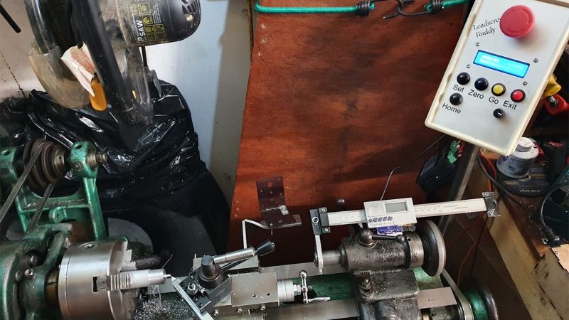
 [Tony Goacher] took this idea a few steps further when he created the Leadscrew Buddy. He coupled a beautiful 1949 Myford lathe with an Arduino, a stepper motor, and a handful of buttons to add some really useful capabilities to the antique machine. By decoupling the lead screw from the lathe’s gearbox and actuating it via a stepper motor, he achieved a much more granular variable feed speed.
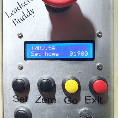
If that’s not enough, [Tony] used a rotary encoder to display the cutting tool’s position on a home-built Digital Readout (DRO). The pièce de résistance is a “goto” command. Once [Tony] sets a home position, he can command the z-axis to travel to a set point at a given speed. Not only does this make turning easier, but it makes the process more repeatable and yields a smoother finish on the part.
These features may not seem so alien to those used to working with modern CNC lathes, but to the vast majority of us garage machinists, [Tony]’s implementation is an exciting look at how we can step up our turning game. It also fits nicely within the spectrum of lathe projects we’ve seen here at Hackaday- from the ultra low-tech to the ludicrously-precise.


https://youtu.be/7QaQrqn4yeI
You should check clough42 Version
https://www.youtube.com/playlist?list=PLDlWKv7KIIr90ZZ7Zqt-ge5nVVdS3WVgg
They don’t have much overlap. This project seems to have focused on feeding to a virtual endstop with adjustable speed. ELS is for synchronized motion with the spindle for cutting threads and does not have travel control.
Its very much the same sort of project – just the clough one is able to synchronise the leadscrew to the lathe to cut threads, nothing to stop you using it to do exactly what this project does – crank a leadscrew around x far repeatedly at y speed.
Nice to see a simpler, easier to understand and use retrofit for better ‘manual’ machining. But for me I’ve been intending to fit a clough one to mine for a while.. It just hasn’t made the top of the list. Being able to turn any thread just electronically is for me a huge win.. And it still drives the leadscrew so tell it you want it to back and forth between x and y is very possible…
clough42’s version is the worst version of them all. It’s overly complicated and it’s basically a way for him to make money off selling you his board. Just use one of the many simpler and cheaper versions.
Clough42 gives nothing better- he posted several videos on his design. Only that the design is unnecessarily complicated. It requires one to buy his buffer board ($20) which has no protection for the onboard TI F280049C (costs $30 bucks or so) 3.3v supply, additional switch 7 seg display for anothet few bucks, and an incremental encoder for another $40 or so. After all the hassle, all you get is an electronic gear box for threading!
Nick Romeo has a simple and similar solution using Arduino and requiring an inex pulse using a magnetic sensor and a single magnet glued to the spindle. And his can be used even as a profiler.
For mini lathes and hobbyist this design is more than sufficient, IMO. I am happy with what I have and Clough42 may be for people with precision that demands a 4k encoder on the spindle and a relatively expensive CPU to do floating point calculations and decode the encoder.
-warrier
If you see protections you can add or improve the design of Clough42’s, why not do it?
Some people like me don’t care about 30$ if we can get something hyper accurate and useful, but all too often, the idea of “simple” ought to be enough is what everyone is trying to do.
Same thinking is what leads so many to use plastic wherever they can as they build a 3d printer, when they know how to use metal and make something better, often when a small jump in cost or skill can make something much more robust and impressive.
I think the Hobby World has enough Simple Solutions on a shoestring budget and hot glue I want to see some hobbyist that actually know how to apply their knowledge to something better make something better who truly bring out the higher-level stuff for people who want to make it like me!
Drew you are both right and wrong -If you like the simpler and cheaper setup and it does what you want that is great.
If like me you want to upgrade your lathe more significantly, enabling more machining options that is also great.
Nothing in the world is one size fits all, and there is nothing wrong with using the tools you have for the problem . I’d go as far as to say there is always a ‘better’ method no matter who you are or how stupidly large your budget and time investment goes. Its always that compromise between the ability to make it within budget (both time and money) and the specifications/features needed.
p.s.
While I agree there are many FDM prints where other methods would be way better – FDM is a cheap effective initial prototype at worst and a functional enduring part at best – its what you do with your waste that matters there. As most alternatives to prints require subtractive machining which is way more wasteful than any FDM print – the energy that goes into making that block of metal is orders of magnitude higher than the filament and the tools are all energy hogs.. – Don’t hate on plastic just because it is plastic and hating that is fashionable now, its got its place…
I don’t subscribe to everybody’s right mentalities. I hate the superficial boiling everything down to a statement that makes everyone feel good.
Its rather simple to me- there are people who want cheap things at all costs that do something. That’s fine for them.
I mostly see that approach in the maker world.
What I rarely see is someone throwing cheap bull out the window, and throwing real serious components at something to absolutely solve a problem with robustness and accuracy in mind above any cost.
It’s those solutions I’m usually looking for.
I do high precision work only- by nature of that, simple and inaccurate just does not satisfy me.
For what this project is- it seems to work fine. I don’t see that dynamic at play so much. It was with someone else complaining about another’s- when it seems they have the chops to go beyond with that idea. If you have the chops- use em! There are plenty of people who want serious solutions to this stuff that don’t cost 30$- maybe a few hundred, but not 10k$, to get impressive results at the simplest non-industrial level.
I agree with your perspective in general.
However, I wouldn’t call 8-bit MCUs, ATmega in particular, “cheap bull” and opposite of “real serious components”. If a talented programmer can solve a problem with an ATmega, and it does a perfect job, then this MCU is suitable for the job, and adding a “more serious” one may just increase costs, power consumption, and require extra components (e.g. logic level converters, power regulators, since I’m guessing all “serious” MCUs are 3.3V and most of them don’t have 5V-tolerant IOs).
In a general purpose computer faster is almost always a benefit. For example, you can have reduced compile times, reduced video encoding times, etc. But when it comes to MCUs, it has particular requirements that it must fulfill in a given time. If it does that, it’s suitable. Nothing is gained by choosing a 10x faster (and perhaps 10x more expensive) part. A faster chip may compensate for sloppy/inefficient programming, though. It can also allow writing less optimized but better architected, structured, readable and maintainable code. Please bear in mind that all of these programming virtues are the reason why today’s amazingly fast (compared to 20 years ago) computers still can slow down to a crawl, run out of RAM, etc. *end of rant*
clough42’s ELS: “This is the firmware for an experimental lathe electronic leadscrew controller”
There are already mature, non-experimental, solutions, which provide everything clough42’s solution does, and more, and cost less to build. (One of) the most capable is DigitalFeed by Oleg A (known as “Russian ELS” / RELS in the English speaking world). Link (in Russian): https://www.chipmaker.ru/topic/118083/
It (optionally) supports cross slide (X axis) power feed, allowing for auto threads, tapers, balls.
I didn’t opt for the ELS due to other reasons though your points are also valid. The math is fragile due to floating point ops and it’s inconvenient to need to compile and flash firmware just to change config/threads.
This one seems to have a more solid foundation and is running on a blue pill to boot.
https://github.com/prototypicall/Didge
Now THIS seems like the ideal solution for both powerfeed and screwcutting issues.
Needs a few other features to work in same fashion as this article’s project, which seems useful too.
Cool find
Indeed as with all things its got limitations. But the wonders of using a software leadscrew with sufficient hardware is you can select what is most important to you (of course you can argue you can do the same with a gearbox for the most part – but then you need a huge box of gears not just a new pile of bits to be loaded into the RAM, which takes up no workshop space!).
One use I was planning to write for the ELS when/if I fit one is for variable thread pitch – so when building mechanisms you can change velocity of the follower over the thread with a fixed motor speed. So you can select the algorithm and calculation method to suit your needs. The electronics don’t have to change, and if you have enough storage you don’t even need to reflash just select the method you want.
Nice project!
Next step is to go grblHAL?
https://hackaday.io/project/165248-mini-lathe-emco-compact-5-cnc-conversion
Seems like a nice project! It’s fun to see more and more people experimenting with this topic and rolling their own solutions. It looks like the first step is implementing a programmable carriage (Z axis) power feed, such as this project provides. After that, just add an incremental encoder to the spindle, and ability to cut arbitrary pitch threads becomes possible to develop, this is a bit of a programming challenge, compared to just the power feed. Some ELS designs go even further and a power cross feed (X axis). With this available, it becomes possible to program fully automatic cutting of threads, tapers, curves, you name it. There are many people in the CNC camp that dismiss the various ELS solutions as not going far enough. They argue that there’s no good reason not to go full CNC. But to each their own, let’s not argue about this here.
For people who are not aware of previously existing alternatives besides this project and clough42’s, I’d like to mention some projects that had been created/perfected years ago.
ELS by John Dammeyer might be the original ELS, it’s at least 10 year old design, replicated and successfully used by many people. Uses a single pulse per spindle rev (it might feel crazy if you compare it with thousand+ PPR encoders used by other projects, however it does appear to work fine, it’s even good enough for Mach3 CNC actually). Uses an Arduino.
https://create.arduino.cc/projecthub/nsr5058/lathe-electronic-lead-screw-52a9c5#widget-comments
https://groups.io/g/E-Leadscrew
DigitalFeed (author’s name) by Oleg A, also known as “Russian ELS” (RELS) on the E-Leadscrew group. Replicated and successfully used by many people. Oleg’s own build uses an 1800 PPR encoder, processed in x2 mode (for a total of 3600 CPR). Also runs on Arduino, which just goes to prove that with some clever and efficient programming, you don’t need floating point or a fast 32-bit MCU to accomplish this. Supports X axis control, allowing for automatic cutting of threads, tapers and balls.
(in Russian) https://www.chipmaker.ru/topic/118083/
AtomicELS by Jon Bryan, a more recent design. Uses a 800 PPR encoder and an Arduino. The UI runs on a 3.2″ Nextion touch-screen display. At least one person had successfully replicated it, and a few more are in progress.
I think it has the sleekest UI of all the ELS designs I’ve seen, although some people argue that with physical controls (buttons, knobs, joysticks) they are able to operate the lathe without looking at the controls. I don’t know how much that would matter in a hobby workshop, but I think that if it is desired, extra physical controls could be added. The Nextion display itself has 8 GPIOs, or the Arduino could handle the extra controls as well.
https://www.youtube.com/watch?v=rKKs4lCEXwE
https://github.com/ccomito1223/ELS-Jon/
https://groups.io/g/AtomicELS
Good leads(crew) man