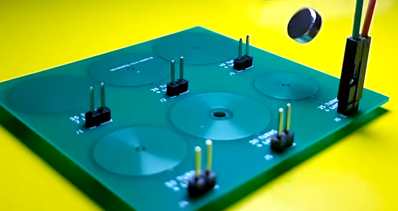
We like to pretend that our circuits are as perfect as our schematics. But in truth, PCB traces have unwanted resistance, capacitance, and inductance. On the other hand, that means you can use those traces to build components. For example, it isn’t uncommon to see a very small value current sense resistor be nothing more than a long PC board trace. Using PC layers for decoupling capacitance and creating precise transmission lines are other examples. [IndoorGeek] takes us through his process of creating coils on the PCB using KiCad. To help, he used a Python script that works out the circles, something KiCAD has trouble with.
The idea is simple. A coil of wire has inductance even if it is a flat copper trace on a PCB. In this case, the coils are more for the electromagnetic properties, but the same idea applies if you wanted to build tuned circuits. The project took inspiration from FlexAR, an open-source flexible PCB magnet.
KiCAD doesn’t like curved traces, but since the file format is open and text-based, it is easy to write scripts that can create shapes for you. [Joan Spark] provided the script. By the way, the goal for these magnets is to improve the mechanical 7-segment display we’ve looked at earlier.
It is really great to be able to work with text files and modify your PCB layouts; it leads to very handy tools. Of course, you can do the same kinds of tricks with gcode, but by that time, you’ve lost a lot of information.


I hope LibrePCB gets this eventually!
And Horizon EDA
You can make yourself a radio like that: http://www.4sqrp.com/cricket40.php
I wonder, would it be possible to use PCB coils like these for a Qi wireless power receiver with a custom shape? How efficient would that be compared to an actual coil?
I’ve spent the last year or so figuring out Q-values for solenoid-shaped coils (tube shaped), and it’s a complex rabbit hole of competing factors. So much so that my next project is to write up a scientific paper on designing high efficiency coils for the HAD journal(*).
That’s a different form factor and the details are different, but I suspect there’s a similar rabbit hole of competing features here, so that any coil you make will be low efficiency.
Specifically, the formula for inductance of a flat coil depends on 5 parameters such as inner and outer diameter, wire thickness, and so on.
Many combinations of these 5 parameters will give you a specific inductance, but there’s no way to judge which combinations are efficient. Literally, the expression for efficiency depends on many factors including the frequency of operation. The efficiency can be calculated, but it’s nigh impossible to use efficiency to inform your choice of parameters.
(My solution is to use software to scan across two parameters such as width and diameter, calculate efficiency at each point, and show a plot of how the efficiency changes. That informs the general “direction” the engineer should choose for those parameters, and gives an accurate estimate of efficiency.)
So any coil one would design will probably have a low Q value, and thus dissipate a lot of the energy as heat.
(*) My current project involves getting a series LC to resonate, and it’s trivially easy to melt the coil due to inefficiencies caused by low-q design.
cool!!
neat optimization trick
I once tried to design an efficient electromagnet for a micro inline solenoid valve type thing, I quickly learned just how hard it was to actually design for efficiency like you said, and it wasn’t even a frequency dependent thing either. I never went ahead with the project past the design stage for the electromagnet 😂
I’m supposed to be taking this course on statistical methods to minimize the number of experiments required to optimize a multivariate system. It seems to me that the experimental problem is similar enough to the problem of parameter selection in a system that can be accurately modeled that the same techniques might be used.
I say “supposed to be” because at just the time I signed up for the course, I got so slammed at work that I just don’t have the mental bandwidth to even watch the videos.
In case anyone is using EAGLE, I have used the spiral-coil.ulp many times to make spiral coils like this. It has worked very well for me.
Clive Sinclair used PCB coils (with square corners) on his radio receivers in the early 70s.
If you are looking for something fun to use the PCB coils for:
https://www.youtube.com/watch?v=3DeOPN1Cl1Y
In the synthesizer world, this would be a game changer if the values could be made correctly to emulate a Moog 907 or 914 formant filter. Many have tried gyrators and failed to get the sound. The clones that use inductors nail it. This could be
a middle ground. I am curious about audio applications.
Don’t forget the other half of your LC circuits!
http://85.226.187.247/use/tuning_caps.htm
http://85.226.187.247/use/tuning_caps2.htm
The problem with this kind of inductor is that FR4 has a very high loss tangent, so they will have very low Q. It’s a nice trick, but I imagine for almost any application an SMT wirewound inductor would be preferable.
You can also use Go: https://github.com/gmlewis/go-gerber/blob/master/README.md
thank you for the lectur
I would like to ask how select the value of the inductance for a parallel sshi circuit?