Let KiCad And Python Make Your Coils

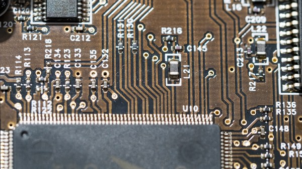
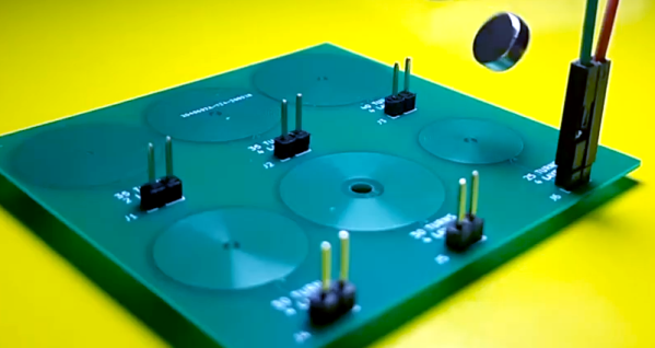
We like to pretend that our circuits are as perfect as our schematics. But in truth, PCB traces have unwanted resistance, capacitance, and inductance. On the other hand, that means you can use those traces to build components. For example, it isn’t uncommon to see a very small value current sense resistor be nothing more than a long PC board trace. Using PC layers for decoupling capacitance and creating precise transmission lines are other examples. [IndoorGeek] takes us through his process of creating coils on the PCB using KiCad. To help, he used a Python script that works out the circles, something KiCAD has trouble with.

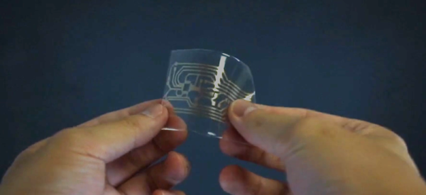
The idea is simple. A coil of wire has inductance even if it is a flat copper trace on a PCB. In this case, the coils are more for the electromagnetic properties, but the same idea applies if you wanted to build tuned circuits. The project took inspiration from FlexAR, an open-source flexible PCB magnet.

Continue reading “Let KiCad And Python Make Your Coils”

Soon… Inkjet Your Circuit Boards

Printed circuit board fabrication — especially in basements and garages — have been transformed by the computer revolution. Before that, people would use a permanent marker or little decals to layout circuit boards prior to etching. Sometimes, they’d do it on film and use a photo process, but they did make decals that you applied directly to the board to resist the etch. Now a team from Georgia Tech, University of Tokyo, Carnegie Mellon, and the University of Nebraska has brought things full circle. Their process inkjet prints silver traces on a substrate that they can then transfer to a circuit board — no etching required.

They start with a standard Epson inkjet with cartridges that have silver-bearing ink. The patterns print on a transfer paper that ensures the particles fuse so there’s no sintering step required to make sure the traces are all conductive. A sticky backing is applied and peels the pattern off the transfer paper. You can see more in the video below.

Continue reading “Soon… Inkjet Your Circuit Boards”

PCB Bring-Up Hack Chat

Join us on Wednesday, April 15 at noon Pacific for the PCB Bring-Up Hack Chat with Mihir Shah and Liam Cadigan!

The printed circuit design process is pretty unique among manufacturing processes. Chances are pretty good that except for possibly a breadboard prototype, the circuit that sits before you after coming back from assembly has only ever existed in EDA software or perhaps a circuit simulator. Sure, it’s supposed to work, but will it?

You can — and should — do some power-off testing of new boards, but at some point you’re going to have to flip the switch and see what happens. The PCB bring-up process needs to be approached carefully, lest debugging any problems that crop up become more difficult than need be. Mihir and Liam from inspectAR will discuss the bring-up process in depth, offering tips and tricks to make things go as smoothly as possible, as well as demonstrating how the inspectAR platform can fit into that process, especially with teams that are distributed across remote sites. If your board releases the Magic Smoke, you’ll want to know if it’s your design or an assembly issue, and an organized bring-up plan can be a big help.

Note: Liam will be doing a simulcast web demo of inspectAR via Zoom. ​

join-hack-chatOur Hack Chats are live community events in the Hackaday.io Hack Chat group messaging. This week we’ll be sitting down on Wednesday, April 15 at 12:00 PM Pacific time. If time zones have got you down, we have a handy time zone converter.

Click that speech bubble to the right, and you’ll be taken directly to the Hack Chat group on Hackaday.io. You don’t have to wait until Wednesday; join whenever you want and you can see what the community is talking about.

Continue reading “PCB Bring-Up Hack Chat”

What’s A Couplate? The Stepping Stone To Integrated Circuits

We are spoiled these days because you can shop online and get all manner of inexpensive electronic goodies shipped to your door. This is due to the fantastic electronic fabrication workflow that has grown into a global powerhouse, facilitated by complex yet inexpensive integrated circuits! But it took a few intermediate steps to get here, and one of those is known as a couplate.

When I was a kid, the big deal was to find an old radio in the trash. You could spend a few hours stripping all sorts of parts from the thing and add it to your collection for a future project. Of course, old radios from the 1970s and earlier had a lot of the usual parts we use today, even though many of them were bigger — no surface mount parts yet. Since older radios were the usual find in a dumpster, tubes were common but you could find some transistor radios.

Once in a while something older. There would be a little box with some wires poking hiding in an old radio from the 1940s or 1950s (too early for ICs). In a way, though, these were predecessors to the Integrated Circuit and they went by a few names, depending on who sold them. PEC (Printed Electronic Circuit), a couplate, or a BulPlate, are all names for hardware that was a stepping stone between discrete circuitry and ICs.

Continue reading “What’s A Couplate? The Stepping Stone To Integrated Circuits”

Printing Circuitry On A RepRap

Over on the RepRap blog, [Rhys] has been experimenting with molten metal to build circuits with the RepRap.

Last June, [Rhys] found a neat alloy made of Tin, Bismuth, and a little bit of Indium that melts at around 130° C, and has just the right properties to be extruded with a standard RepRap setup. The results were encouraging, but the molten metal quickly dissolved the brass and aluminum nozzles [Rhys] was pushing liquid metal through.

The solution to this problem was solved by anodizing the heck out of a RepRap nozzle to make a hard, protective oxide layer. Already [Rhys] has logged hundreds of hours squirting molten metal out of his RepRap with no signs of any damage to the nozzle.

Since [Rhys] figured out how to print in metal, he whipped up an extremely minimal Sanguino board. You can see this RepRapped PCB running a LED blink program after the break. Now to work on the RepRap pick and place…

Continue reading “Printing Circuitry On A RepRap”