A recent writeup by Tom Nardi about using the 6502-based NES to track satellites brought back memories of my senior project at Georgia Tech back in the early 80s. At our club station W4AQL, I had become interested in Amateur Radio satellites. It was quite a thrill to hear your signal returning from space, adjusting for Doppler as it speeds overhead, keeping the antennas pointed, all while carrying on a brief conversation with other Earth stations or copying spacecraft telemetry, usually in Morse code.
The Manual Way
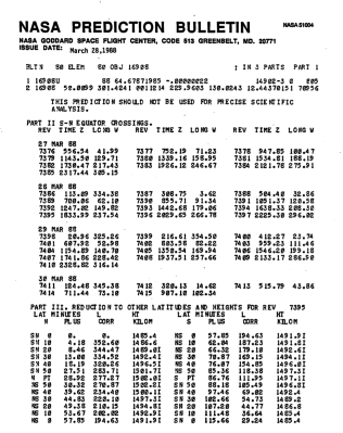
Pulling this off was quite a production in the pre-Internet days. To begin with, you needed data about each satellite’s orbit. This was obtained by signing up to a real-paper mailing list from NASA’s Goddard Space Flight Center. An envelope arrived about twice a week by mail containing a stack of NASA Prediction Bulletins for the satellites you had requested. These contained the orbital parameters in what’s known as two-line element (TLE) set format, which you had to then type into your computer for processing. When we communicated with Space Shuttles, we would get the preliminary and later actual TLE data from someone within NASA by phone or FAX.
Unlike geostationary communications satellites, Amateur radio satellites are typically launched in polar orbits which take between 90 to 120 minutes to complete one revolution of the Earth. To communicate through one of these satellite, first we needed to know when a particular satellite would pass over Atlanta.
To solve this problem, I wrote a Fortran program on the campus mainframe computer, a CDC Cyber 74, a real computational beast of the day. This program propagated the state vector given by the TLE data, and generated a list of orbits which passed over Atlanta. These passes were characterized by the maximum elevation, the duration of the pass, the AOS and LOS (Acquisition / Loss of Signal) times, and the distance at closest approach. We humans would filter this list even further, ignoring passes that were very short or that occurred when we would be asleep or attending class — after all, the reason we were at GA Tech was to study hard, learn a lot, and graduate with a degree.
Object                  Orbital altitude  Inclination  Orbital period
======================  ================  ===========  ==============
Oscar 8                  900 km circular  99 degrees   103 minutes
Radio Sputnik 5,6,7,8   1600 km circular  83 degrees   120 minutes
Space Shuttle STS-9      250 km circular  57 degrees    90 minutes
Space Shuttle STS-51F    315 km circular  50 degrees    91 minutes
The satellites of the day had two popular modes. Mode A was easiest to use for most Hams, the uplink was in the 2 m band, and the downlink was on 10 m. Mode J also used a 2 m uplink, but the downlink was in the 70 cm band. A typical Ham satellite station would use a stationary horizontal loop antenna for 10 m reception. The 2 m and 70 cm antennas were usually Yagis, mounted on common rotatable elevation boom which was itself mounted on a vertical mast that could be rotated in azimuth. Ten meter reception was simple, no antenna movement required. Steering the Yagi antennas, however, was quite a task.
Having selected a suitable orbit, next we had to make those Yagis follow the path of the satellite. In Amateur satellite stations, this is a completely open-loop process. You calculate where the satellite will be at a certain time, and drive the antennas to that point in space. If you remember the old home steerable TV antennas, before cable TV and streaming, the arrangement in a Ham shack is very similar. There is a rotator control box for each rotor, with an analog meter indicating direction, modern ones being digital, of course. These control boxes usually had three buttons for steering: Left, Right, and Brake release.
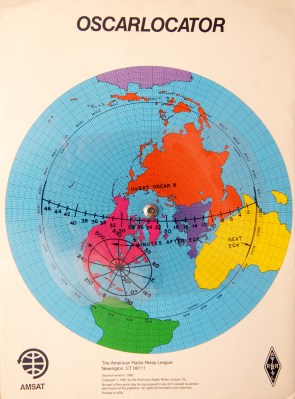
To follow the satellite, we had a couple of techniques available. One method used a graphical overlay of the satellite’s ground track and footprint on top of a polar projection map of the Earth. By rotating the ground track overlay to match the orbit’s position as given by the orbital parameter with the coolest name, Right Ascension of the Ascending Node, we could visually see the satellite’s path over our station. The ground path overlay has time tick marks, and the footprint overlay has azimuth lines and elevation rings. This crude graphical technique provides the basic information needed to track the satellite, within the broad beamwidth of our antennas. We also had to keep our clocks synchonized to WWV or WWVH — no Network Time Protocol back then.
A second technique was more precise, but required a trip across campus. Using another Fortran program, I could print a table of time, azimuth and elevation angles for a desired orbit. The operator wouldn’t have to interpolate angles from the graphical overlays: the numbers are clearly shown on the computer printout paper. Getting this data from the campus computer wasn’t trivial, however. Usually I would visit the computer center building across campus, login to my account at a terminal, and type in the data by hand. Upon execution, the program would generate a printout.
Then I had to wait at the output counter for the operator to separate and distribute the printouts to all of us impatient users. We felt so lucky when the club obtained a portable printing terminal with a built-in acoustic modem. This meant we could dial into the mainframe and run the programs remotely, and get our orbit schedules and tracking tables immediately without crossing campus — at the blazingly fast speed of 300 baud!
While all these machinactions were certainly within our grasp, it took quite a bit of effort and advance planning. And while a lone operator could communicate with a satellite, two people were better — one to operate the radios, the other to steer the antennas. I recall two events from this period which led me to consider a computer controlled project. First of all, we inherited two Commodore PET computers from one of the EE professors. Secondly, we had an ongoing issue controlling equipment up on the roof of the 5th floor from our shack located at basement level. There just weren’t enough wires to do all the things we wanted even for normal HF operations, much less satellite tracking.
Commodore PET to the Rescue
The Commodore PET computers we had were modified from their standard factory condition. They had full-size external keyboards, so you didn’t have to use the Chiclet keys. The internal memory had been upgraded to 32K RAM. My report from 1983 says this expansion memory card also had two general purpose 8-bit TTL output registers, which were used to talk to the outside world.

As shown in this diagram, the PET computer talks to two devices — the Rotor Control Interface selects and operates the rotor boxes, and the Digital Serial Transmitter, essentially just a UART that sent data serially to the roof to remotely control a variety of equipment. Rotor control was fun, because we only had one rotor control cable between the shack the the roof. I had to implement 8P3T switches out of relays and multiplexed the cable between rotors. This means that only one rotor could rotate at a time, but this wasn’t a severe constraint for our purpose.
Besides the rotator control signal multiplexing, there was quite a bit of auxilliary equipment on the roof which had to be remotely controlled. As shown in the diagram, we had RF coaxial relays to switch VHF/UHF antenna polarization, and to switch between 10 m and 70 cm downlink signal paths. In addition, there were preamps, down-converters, and power amplifiers which had to be turned on and off. Except for rotor multiplexing, most of these were static setups for the duration of a satellite pass, although the PET had full control of everything over this interface. 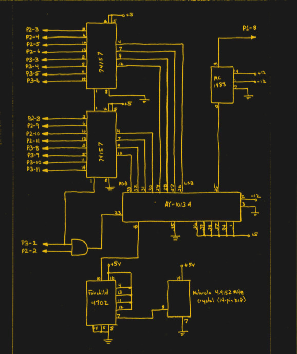 We made a UART interface connected to one of the PET’s TTL output registers to send this control data serially to the roof for control. I hand-drew all the schematics and hand-taped the PCB artwork – no KiCad back then.
I very quickly identified a problem having the PET control of all this rooftop gear, which was not related to satellite operations at all. The PET wasn’t running 24/7, and it was slow to boot and load up from cassette tape. Operators who just needed to control relays on the roof for HF operations didn’t want to wait 10+ minutes to boot the PET. In fact they were quite vocal about it. So I added a manual control panel to bypass the PET. This philosophy has served me well over the years — computer control is great, but there are times when you need manual control, if only for testing.
We Don’t Need Closed Loops
There was still one problem with this setup — you might have noticed there is no feedback. There was a method for the PET to read signals, but despite trying a variety of methods we couldn’t get a stable enough feedback within our limited budget and limited mechanical skills. The azimuth rotor, which had an integrated feedback signal, would have been the easiest to monitor. But the elevation rotor we used didn’t have any such feedback.
We tried a long rod with a lead weight at the bottom, attached to a potentiometer. When the boom rotated up and down in elevation, the rod always pointed down. Good idea on paper, didn’t work so well in practice. We briefly played with synchromotors, which were really cool. Turn the shaft of one motor and the other motor across the room also turned the same amount, connected only by a few wires. But even these few wires were too many for our peculiar installation.
In the end, I concluded that for the satellites of interest and the antenna beamwidths involved, running the antenna rotation controls open loop was workable. To be sure, it caused a lot of headaches to procedurally check alignment before a pass, but once the pass began it worked as desired. I was continually tweaking the computer model of the antenna rotation, both the mathematical model and the constants such as dead-time, rotation speed, acceleration, etc. It was a crude solution, but it got the job done within our limited budget.
Aside: Zenith crossing and three axis mounts
You might think that a satellite passing directly overhead would be perfect — it is as close as possible to your station. Well, that’s not necessarily good. The problem is that when the satellite passes overhead, and the elevation angle approaches 90 degrees, the azimuth rotor will suddenly have to spin at an incredibly fast rate to keep pointed. There are ways to mitigate this — one method is to accept some pointing error and steer the antenna in a small circle around zenith — a circle whose diameter is determined by the speed of the satellite and the maximum speed of your rotor.
A more elegant solution, but mechanically complex, is to add a third axis of rotation. Two of the rotors are positioned before the satellite pass so that the antenna boom connected to the third rotor is perpendicular to the orbital plane. This way, only the third rotor is used during the satellite pass, and the other two rotors remain fixed.
Where is OSCAR?
Providing the PET with interfaces to the real world was only half the battle. I still needed a way to calculate the satellite’s position. And while it was great to have a computer in the shack, the PET computer was thousands of times less powerful than the campus mainframe. There was no GUI, no tracking map of the Earth, just updating data fields on a text-based status screen.
I remember one major issue in the software development, however. There were several programs floating around the community those days for tracking satellites, and I hand typed one of the popular ones into the PET. I contacted the author of this program to let him know about my school project and get his permission.
But to my surprise, he replied “No, you can’t use my software”. Just a minor setback for a young college student who doesn’t know his limitations — I went to the GA Tech library, checked out a couple of books on orbital mechanics, and wrote my own algorithms. Surprisingly, the fundamental Keplerian laws and equations for orbital bodies aren’t that difficult to understand and calculate. Alas, when you solve for the antenna pointing angles to the satellite, it results in a transcendental equation. Solving that on the mainframe took milliseconds, but it was painfully slow on the PET. Over a month or so that followed, I confined myself to programming at home all weekend, developed an life-long addiction to caffeine-laden diet colas, and emerged with a working program.
Upgrades
The manual controls for rooftop equipment were non-intuitive. You were literally toggling address and data bits into a UART. This could have been improved, of course, but a few of us began to question the original “no more wires can be routed to the roof” constraint. It turns out that it was indeed possible, with a bit of effort. A larger cable for signaling was pulled to the roof, and an improved interface panel was made. Furthermore, the PET was showing its age, too, so we upgraded to the Commodore C64 — with floppy disk storage. I made a new, smaller rotor control interface that connected to the C64’s user port and controlled the rotors by relays.
Successful Ops
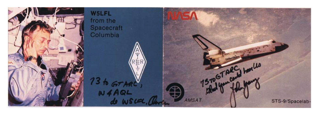
The system, while a bit finicky, did serve us well for a few years. Not only were we able to communicate over Amateur Radio satellites, but quite proudly we contacted the first two astronauts allowed to operate from the Space Shuttle under a new program called SAREX. In Nov 1983 Dr. Owen Garriott (W5LFL) heard us on Columbia’s STS-9 mission, which was piloted by our own GA Tech alumni Dr John Young. We were also proud of our own recent club alumni, Jim Worsham, W4KXY, who was on the team at Motorola that designed and built the custom radio used by Dr. Garriott.
Again in Aug 1985, we contacted Dr Tony England (W0ORE) on Challenger’s STS-51F Spacelab mission. Videos were made of these efforts, which you can see in the links below.
- YouTube: Receiving SSTV from STS-51F
- YouTube: Attempted Contact with STS-51F
- YouTube: Successful Two-way Contact with STS-51F
Future?
I challenged myself last year to build a miniature version of this project that fits in an Altoids can. It’s on the back burner for now, until I can track down a copy of the original software. Stay tuned…
Wrapping Up
A couple of years after I graduated, the company I worked with generously let me manufacture and market this C64-based tracking system under the unimaginative name Satellite AutoTracker. That’s a story for another day.
I can’t overemphasize the impact this project had on me. The act of conversing with another radio station via a satellite pulls together so many engineering and science disciplines, from the physics of orbits and Doppler shifts to the minute details of learning to build PCBs to the overall system engineering efforts to make it all play together. Each one of these were interesting in and of themselves, but it was just plain awesome when it all successfully meshed together and worked.
I learned a lot building this project, but it didn’t seem like learning because it was so fun. That, folks, is the best way to learn.


Wow. Great work and very detailed description. You did more with PET than most did with Pentiums. Persistence is key.
I should note this wasn’t done overnight. I’d guess the whole thing stretched over a year or more, with many incremental steps and experiments along the way. About the PET itself, it’s funny to say, given how underwhelming a C64 is compared to today’s computers, but it was a huge step up in performance and ease-of-use when we migrated away from it to the C64. While the PET was more than adequate for hardware control and so-so for orbital calculations, it was too slow for any decent user interface. The programming experience, even with the full size keyboard, ranged from tolerable to downright unpleasant due to the small screen and cassette tape storage.
Weird, PET and C64 should be pretty equal in terms of number crunching performance?
As I recall in the days of OSCAR 6, W1AW transmitted tracking information as part of its regular bulletins.
But a new satellite was a big event back then. Maybe it tapered off as more went up.
That first picture in the article gets a 12 out of 10 for retrocool!
Yeah, right?
HP scientific calc in lower right-hand corner. Just sayin. This was the best desk in 1985.
Zooming in, I’m pretty sure that’s my first calculator: an HP-25, without the “C” option. You turn it off, you lose all memory.
I came to the party late and was fortunate enough to use a program from AMSAT called “The Station”. I fed it the Keplerian data files from NASA emails and it controlled the 2-meter uplink VFO on my Yaesu FT-847 and corrected for Doppler shift. Fun times using the Russian RS-12/RS-13 LEO satellites.
This reminds me of my father and I working the Mir station via packet radio (probably on the 2m band) way back when I was 12. He used a program on his Commodore 64 to determine when the station would be overhead. It was an experience I’ve never forgotten.
I can remember back in the early 1980s buying a book at a radio rally (from the RSGB I suspect) all about amateur satellites and satellite tracking. The book was 90% program listings in BASIC to create and list various satellite passes for several satellites. They ALL had to be typed-in manually, and a ‘certain amount’ of modification had to be done to adapt them to the version of BASIC you were using, and the idiosyncracies of the device.
This was all pre- ‘home computing’, but I had access to a microcomputer at work (anybody remember the Intertec Superbrain?) with twin floppies. We only used it for word-processing (WordStar anyone?) but I had found a second floppy in the box which was a CP/M disk; I quickly became an expert in CP/M compared to anybody else at work, and I would spend an hour or more after work making the various tracking programs work as I needed them.
The worst part (for me) was having to manually enter all the TLE data; it was only ever available as a print-out so the only way to use the data was to type everything, check it, double check it, try a test run, see that there were errors, and then discover that the TLE data was wrong! But, great fun, in hindsight.
Graham, you might enjoy reading this interesting writeup about Dr Kelso and his discovery of a checksum error in the NASA TLEs back in the 80s. Like you, he was typing them into his computer, and eventually wrote some software to check the data using the checksum digits which were part of the TLE format. He noticed that unexplainable checksum errors would happen infrequently, and eventually tracked down the source of the problem: https://www.celestrak.com/NORAD/documentation/checksum.php
Nice work! I also have a satellite tracking project, haven’t done anything on it for awhile but it is active and I have gotten quite a bit further than what I’ve documented so far:
https://hackaday.io/project/5358-keplermatik
Cool to see this. If anyone wants to try some retro computer satellite tracking, disk images for AMSAT’s QUIKTRAK program for the Commodore 64 and Apple II are available on AMSAT’s website at https://www.amsat.org/flashback-friday-satellite-tracking-with-quiktrak-for-the-commodore-64-and-apple-ii/
I also have a tape with the Timex Sinclair 1000 / Sinclair ZX-81 tracking program called AMS-81. I need to digitize that tape and get it posted.
Nice story, Chris! Can you make available the Satellite AutoTracker program for the Commodore 64?
I certainly would, Robert, if / when I find it. I’ve been poking around the last year or so, low-level of effort, trying to find it. Tracking down one of the few Satellite AutoTrackers would be good first step. I’ve checked with the AMSAT historical tracking software collection, and some friends of mine from those days. So far, no luck.
A9 #00
My son has unearthed a stash of old AutoTrackers. I no longer have an excuse to re-implement this system in modern format. I checked my original comment from last year, and I said “bar of soap”, not “Altoids mint can”.
https://hackaday.io/project/175877-bar-of-soap-satellite-tracker