
Circuit simulations are great because you can experiment with circuits and make changes with almost no effort. In Circuit VR, we look at circuits using a simulator to do experiments without having to heat up a soldering iron or turn on a bench supply. This time, we are going to take a bite of a big topic: op amps.
The op amp — short for operational amplifier — is a packaged differential amplifier. The ideal op amp — which we can’t get — has infinite gain and infinite input impedance. While we can’t get that in real life, modern devices are good enough that we can pretend like it is true most of the time.
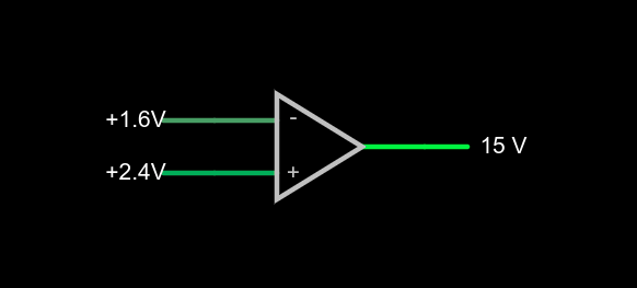
If you open this circuit in the Falstad simulator, you’ll see two sliders to the right where you can tweak the input voltage. If you make the voltages the same, the output will be zero volts. You might think that a difference amplifier would take inputs of 1.6V and 2.4V and either produce 0.8V or -0.8V, but that’s not true. Try it. Depending on which input you set to 2.4V, you’ll get either 15V or -15V on the output. That’s the infinite gain. Any positive or negative output voltage will quickly “hit the rail” or the supply voltage which, in this case, is +/-15V.
Practical Concerns
The biggest omitted detail in the schematic symbol above is that there’s no power supply here, but you can guess that it is +/- 15V. Op amps usually have two supplies, a positive and a negative and while they don’t have to be the same magnitude, they often are. Some op amps are specifically made to work with a single-ended supply so their negative supply can connect to ground. Of course, that presupposes that you don’t need a negative voltage output.
The amount of time it takes the output to switch is the slew rate and you’ll usually find this number on the device datasheet. Obviously, for high-speed applications, a fast slew rate is important, particularly if you want to use the circuit as a comparator as we are here.
Other practical problems arise because the op amp isn’t really perfect. A real op amp would not hit the 15V rail exactly. It will get close depending on how much current you draw from the output. The higher the current, the further away from the rails you get. Op amps will also have some offset that will prevent it from hitting zero when the inputs are equal, although on modern devices that can be very low. Some older devices or those used in high-precision designs will have a terminal to allow you to trim the zero point exactly using an external resistor.
Op Amps Can Provide Steady Voltage Under Variable Load
Rather than dig through a lot of math, you can deal with nearly all op amp circuits if you remember two simple rules:
- The inputs of the op amp don’t connect to anything internally.
- The output mysteriously will do what it can to make the inputs equal, as far as it is physically possible.
That second rule will make more sense in a minute, but we already see it in action. Set the simulator so the – input (the inverting input) is at 0V and the noninverting input (+) is at 4V. The output should be 15V. The output is trying to make the inverting input match the noninverting one, but it can’t because there is no connection. The output would like to provide an infinite amount of voltage, but it can only go up to the rail which is 15V.
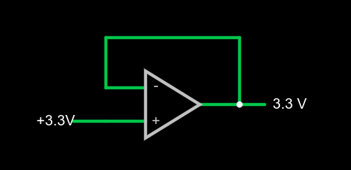
We can exploit this to make a pretty good x1 amplifier by simply shorting the output to the – terminal. Remember, our rules say the input terminals appear to not connect to anything, so it can’t hurt. Now the amplifier will output whatever voltage we put into it:
You might wonder why this would be interesting. Well, we will learn how to increase the gain, but you actually see this circuit often enough because the input impedance is very high (infinite in theory, but not practice). And the output impedance is very low which means you can draw more current without disturbing the output voltage much.
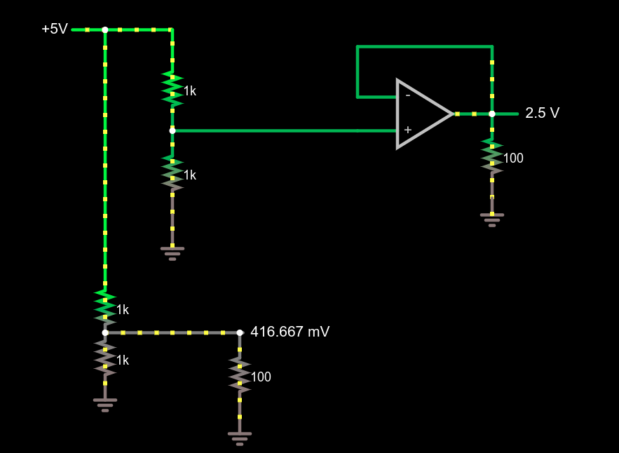
This circuit demonstrates the power of a 1x amplifier. Both voltage dividers produce 2.5V with no load. However, with a 100 ohm load at the output, the voltage divider can only provide around 400mV. You’d have to account for the loading in the voltage divider design and if the load was variable, it wouldn’t be possible to pick a single resistor that worked in all cases. However, the top divider feeds the high impedance input of the op amp which then provides a “stiff” 2.5V to whatever load you provide. As an example, try changing the load resistors from 100 ohms to different values. The bottom load voltage will swing wildly, but the top one will stay at 2.5V.
Don’t forget there are practical limits that won’t hold up in real life. For example, you could set the load resistance to 0.1 ohms. The simulator will dutifully show the op amp sourcing 25A of current through the load. Your garden-variety op amp won’t be able to do that, nor are you likely to have the power supply to support it if it did.
What’s Being Amplified?
This is an amplifier even though the voltage stayed the same. You are amplifying current and, thus, power. Disconnect the bottom voltage divider (just delete the long wire) and you’ll see that the 5V supply is providing 12.5 mW of power. The output power is 62.5 mW and, of course, varies with the load resistor.
Notice how this circuit fits the second rule, though. When the input changes, the op amp makes its output equal because that’s what makes the + and – terminals stay at the same voltage.
Of course, we usually want a higher voltage when we amplify. We can do that by building a voltage divider in the feedback loop. If we put a 1:2 voltage divider in the loop, the output will have to double to match the input and, as long as that’s physically possible, that’s what it will do. Obviously, if you put in 12V it won’t be able to produce 24V on a 15V supply, so be reasonable.
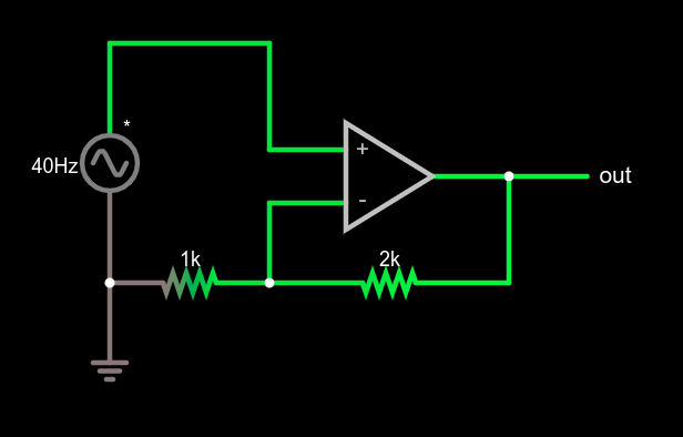
This type of configuration is called a non-inverting amplifier because, unlike an inverting amplifier, an increase in the input voltage causes an increase in the output voltage and a decrease in input causes the output to follow.
Note that the feedback voltage divider isn’t drawn like a divider, but that’s just moving symbols on paper. It is still a voltage divider just like in the earlier example. Can you figure the voltage gain of the stage? The voltage divider ratio is 1:3 and, sure enough, a 5V peak on input turns into a 15V peak on the output, so the gain is 3. Try changing the divider to different ratios.
What’s Next?
While it isn’t mathematically rigorous, thinking of the op amp as a machine that makes its inputs equal is surprisingly effective. It certainly made the analysis of these simple circuits, the comparator, the buffer amplifier, and a general non-inverting amplifier simple.
There are, of course, many other types of amplifiers, as well as other reasons to use op amps such as oscillators, filters, and other even more exotic circuits. We’ll talk about some of them next time and the idea of a virtual ground, which is another helpful analysis rule of thumb.


Op amps are pretty dang cool, with a lot of neat circuits you could build using them. I actually just put the finishing touches on my first actual op amp design and sent the design files over to one of the big PCB houses to take advantage of their dirt cheap 4-layer deal they’re offering until tomorrow: A 3-channel transimpedance amplifier with selectable gain and a variable bias voltage set via the non-inverting leg that gets applied to the inverting “input” side (I put input in quotes because in reality it can both source or sink current to whatever it’s connected to), and it can do that with minimal external circuitry.
I object to his rule:
> 2. The output mysteriously will do what it can to make the inputs equal, as far as it is physically possible.
It is not at all what an opamp does, and this should have been clear from the earlier example, where 1V6 and 2V4 is put on it’s inputs and the output saturates to one of the voltage rails.
A much better rule is to remember that if the non inverting input has a higher voltage than the inverting input, the output goes up, and if the other is higher the output goes down, and often the circuitry around it is built in such a way that the output is stabilized. This is no magic, and treating it as magic just gives you an excuse for not understanding how opamps work.
A very good (and free) document about opamps and how they work is SLOD006 A.K.A “Opamps for Everyone” from Ti, written by Ron Mancini. There are several versions of it on the ‘net. Personally I prefer one of the oldest, written in early ’70-ies.
Or more specifically, the output voltage is the difference in voltage between the two inputs multiplied by the op amp’s open loop gain. Since this gain is generally quite large, even a small differential voltage at the inputs will make the output hit its rails before it even achieves maximum gain.
In practice, you can’t generally rely on the open loop gain as this varies significantly for a given part. As an example, per the TLC27L1’s datasheet, the open loop gain can vary between typical and minimum values by a factor of 20!
I’m not saying it’s the real action. I’m saying it is a useful analysis idea which covers the common operating conditions.
It is not useful. It is harmful because it is unreliable because you skip a step, and it only works in your “most common” operating condition. You should always start analyzing a new circuit by verifying if the circuit surrounding the opamp results in this behavior or not.
If you teach it as a “rule” that does “magic” you’re learning bad habits to newbies.
Opamps are used as comparators, in oscillator circuits and in setting for example (adjustable) current limits in power supplies. If you start with giving these false rules because there “useful in some situations” you quickly get stuck when trying to analyze such circuits.
If however, you start by teaching what an opamp really does, then once people understand the basics they can expand upon this, and they will discover that that the surrounding circuitry often results in the input voltages being nearly the same.
Well, we’ll just have to agree to disagree then. I’ve had a lot of success with it with students and while I didn’t learn it there, even The Art of Electronics uses the same “rules” (I had to look up to make sure). So if I’m wrong I’m in pretty good company.
Personally, I have found that getting people to have an intuition about things helps them learn the rigor later. Kind of like most math. I can teach the math behind, say, the derivative and hope students can deduce what it all means in the real world, or I can show some examples and give them a feel for it and then back up into the actual math. But I don’t need to convince you. You can teach it however you like and I’ll continue to teach it how I like.
Thank you for the article Al! I knew very little about op-amps and now I know slightly more. Perhaps it’s the encouragement I need to try something with one of the TL072s that my EE friend gave me excitedly.
I’ve also looked it up int “The Art of Electronics”.
In the introduction they tell at least twice that an op-amp is a high gain differential amplifier, and there is indeed a sentence that states: “The output attempts to do whatever is necessary to make the voltage difference between the inputs zero.” And two sentences before it is written that this is only true when the opamp is used with negative feedback.
Your first rule also make no sense whatsoever:
“The inputs of the op amp don’t connect to anything internally.”
If this was true, then why bother to connect anything to it?
The Art of Electronics writes it as:
“The inputs draw no current.”
In the end it means you’ve turned both “rules” into gibberish or at best half truths. It is because of teachers like that that I’ve lost interest in school.
Absolutely agree. There are many situations where it’s better for understanding the basics of anything (not just electronics) by teaching simple rules (even if they’re not completely accurate or miss a step), however at a later stage (either in the lesson or the course) to elaborate on the specifics and ensure that students understand the more complex rules. This is how we teach! You teach how to use a tool then you teach why we use that tool when the student has the grasp of what the tool is.
please enlighten me on how the rule breaks down in the first case? Where does it break down ever? Are there any modern op amps with open loop gain low enough to not result in the same max voltage output?
This rule was very useful to me, as a hobbyist. in theory I should learn everything with rigorous study and take no shortcuts. In practice, id prefer to be making stuff and can get by using this simplification, as taught to me by Dave Jones from eevblog.
I dont think anybody believes schools should end their op amp lessons with these rules, but if I want a quick and dirty result it works for me. i have not been led too far astray with it yet.
The Art of Electroncis writes it down clearly and logically:
Here are the simple rules for working out op-amp behavior with external negative feedback. They’re good enough for almost everything you’ll ever do.
First, the op-amp voltage gain is so high that a fraction of a millivolt between the input terminals will swing the output over its full range, so we ignore that small voltage and state golden rule I.
I.The output attempts to do whatever is necessary to make the voltage difference between the inputs zero.
Second, op-amps draw very little input current (about50 pA for the inexpensive JFET-input LF411, and often less than a picoamp for MOSFET-input types); we round this off, stating golden rule II.
II.The inputs draw no current.
———————-
So it clearly says it only works when negative feedback is applied. And it does not work this way when an opamp is used with positive feedback, for example when used as a schmitt-trigger.
Also, in some applications the output gets inverted by an extra transistor, in such a case you have to “swap” the positive and inverting inputs to get negative feedback.
A rule you can ALWAYS *1) fall back on is that an opamp amplifies the difference of the input voltages and amplifies that a lot (approx 100.000x) and puts that voltage on the output.
*1). “normal” opamp under “normal” operating conditions (power is connected (and such)).
* Here’s a link to download the TI app note “Op Amps for Everyone (Rev. B) TI slod006B”. Unfortunately it seems to have vanished from the TI web site, or at-least I can’t find it.
https://web.mit.edu/6.101/www/reference/op_amps_everyone.pdf
* This site is a nice resource for Op-Amp learning-by-example:
Analog Devices Inc., “Analog Electronics”
https://www.analog.com/en/education/education-library/tutorials/analog-electronics.html
I Googled searched using “SLOD006” by itself and the first result was a MIT address which when clicked upon successfully downloaded the file.
The implied detail needed to make the claim true is that your circuit is correct.
Notice that the op amp isn’t claimed to “magically” make its inputs equal; just the internal mechanism is left mysterious. It still relies on you having built a circuit with feedback such that this does indeed happen. It is important to treat it as a black box, because the best models for understanding the internals are to presume the op-amp is made just from analog transistors configured mostly as current mirrors. But an op-amp made that way lacks the performance of a more complicated design that is internally clocked. And because some engineers, or aspiring engineers, get really hung up on words that they think are incorrect, it is important not to try to describe the insides of the op-amp; instead you say it straight, “look just let the mechanism be a detail and learn to think of it as a design block.” If they need to understand why the implementation is the way it is, they’ll figure it out not here, but when they’re trying to understand successive approximation ADC circuits. Then it is all more obvious, and then once you have that, you go back the op amps and understand why people who use the word “chopper” (which has pejorative intent) don’t understand what op-amps are supposed to do; they’re supposed to try to make their inputs equal when connected in a certain way!
And yes, SLOD006 is in my app note library, too.
You can’t blame anybody, this is the standard formulation in almost all the books. Therefore it isn’t wrong; the choices are that it is relevant to you, or it isn’t relevant to you. It helped you understand, or it didn’t. It isn’t wrong; you already know it was double-checked by everybody and found correct, that’s why it is in all those books.
Actually it’s very useful as a first order analysis to consider the op amp output does what it needs to make the inputs equal. Op amps are so good these days that this approximation is usually all you need to understand a circuit.
This would lead one to incorrectly interpret that an op-amp circuit with positive feedback would “magically” turn itself into an inverting amplifier internally.
I’ve been impressed by KiCAD’s nice integration of ngspice within KiCAD itself. You have to work a little bit to get opamps working in the sim as most of the opamps in the available libraries don’t have spice models, but there are ones available. For a lot of people, seeing a nice graphical input and output waveform helps to understand what opamps are doing.
One of my favorite books (across all subjects) is “Introductory Operational Amplifiers and Linear ICs: Theory and Experimentation” by Robert Coughlin and Robert Villanucci. It’s a fascinating deep dive into op-amps and their applications to all kinds of everyday problems, as well as a secondary focus on analog computing (it’s an older book), which actually really helps drive home the mathematics behind op-amp circuits. I would highly recommend tracking down a copy for anyone with interest in not just op-amps but analog circuitry in general.
Connecting both inputs of an OpAmp to low-impedance voltage sources is not a good idea, it can instantly fry the input stage of some OpAmps like the NE5534 as this thing has two anti-parallel diodes between its inputs. Always read the data sheet before attempting to misuse an OpAmp as a comparator.