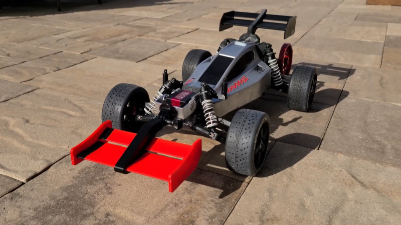
Motorsport became obsessed with aerodynamics in the middle of the 20th century. Moving on from simple streamlined shapes, designers aimed to generate downforce with wing elements in order to get more grip between the tyres and the track. This culminated in the development of active aero, where wing elements are controlled by actuators to adjust the downforce as needed for maximum grip and minimum drag. Recently, [Engineering After Hours] decided to implement the technology on his Traxxas RC car.
The system consists of a simple multi-element front wing, chosen for its good trade-off between downforce and drag. The wing is mounted to a servo, which varies the angle of attack as the car’s pitch changes, as detected by a gyroscope. As the car pitches up during acceleration, the angle of the wing is increased to generate more downforce, keeping the nose planted.
The basic concept is sound, though as always, significant issues present themselves in the implementation. Small bumps cause the system to over-react, folding the wing under the front wheels. Additionally, the greater front downforce caused over-steer, leading to the install of a rear wing as well for better aero balance.
Regardless of some hurdles along the way, it’s clear the system has potential. We look forward to the next build from [Engineering After Hours], which promises to mimic the fan cars of the 70s and 80s. If you’re looking to improve aero on your full-size car, we’ve got a guide to that too. Video after the break.
[Thanks to Zane Atkins for the tip!]


This is screaming out for a pushrod from the servo to the winglets to adjust the angle.. tilting the whole nose barely made sense for Concorde, and it wasn’t 1cm off the ground…
Fun to see it function though.
The Concorde issue was visibility on landing during high angle of attack. Pilot could not see the runway. The drooped nose did not work at high speed so there wasn’t much choice.
Yes I know – but its the only example I could think of that bends the whole nose around for any reason – things like car ferries might drop a ramp, some heavy lift aircraft open with a door like hinge – nothing but the Concorde I could think of points its whole noise at the ground on purpose, and being up on its wheels at the time that nose is a meaningful distance off the ground.
Its the most backwards way to do active aero I think I’ve ever seen, and that includes some of the earliest attempts at powered flight…
Were video cameras and monitors too difficult to get reliable enough back then?
IMO they’re not reliable enough now when you’ve got to worry about hitting an object the size of a planet gently.
I wouldn’t say it was the reliability personally – more the speed of travel and distances to view – you want to be able to see the runway from a great distance out when on approach, but also want to see the folks/ service vehicles and markings on the tarmac while taxing. Thats two vastly different focal lengths – and the zooming between them – back then probably easy to drop the nose.
Hmm. I wonder how small a model can get before Reynolds Number becomes more important than Mach Number in the aero design ?
Why not implementing active systems to control the torque and rpm of the wheels
Input:
– wheels / Incremental resolvers
– gyro
output:
– torque/Amp limit on the motor control
or
Input:
– angle/distplacement of your front shockabsorbers
output:
– torque/Amp limit on the motor control
Reasoning:
When your car is already lifting itself up, it has already increased the aerodynamic lift surface dramatically, (think about F1 crashes it’s already beyond a tipping point)
When you put a limit at a point before it can lift you will add more stability + you can further increase stability by adding active aerodynamics.
Someone who attempts FEM of the tires should probably look into how sensitive the L/D curve and Cl of the wing is to small changes in angle of attack. Also the acceleration error in the leveling gyro.
That said, it’s good to see he’s going for the direct fan-driven downforce on the next build.
I actually did in the first video…this one just reused the exact same wing arrangement. This car is draggy like all cars of this style, but I don’t believe top speed is drag limited anyways.
I usually only try to cover 1 key technical concept from an analysis standpoint, and this one was a use case for a rotational FEA. The first video was for a rough order wing analysis. The fan car will probably be over a target pressure drop across a surface but it’s a pretty challenging project given how sensitive the car is to sealing against the floor.
Biggest issue for an RC vehicle is the weight of the active aero system vs the speed gained. The scale factor does not really apply to the control electronics so the weight penalty is much worse for the small vehicle vs something like a full scale F1 car. I suspect the additional weight is not worth the gains in the scale vehicle. Nice experiment though.
Actively controlling torque would be cooler.
Using a fan to actively suck/blow the car to the ground would be epic.