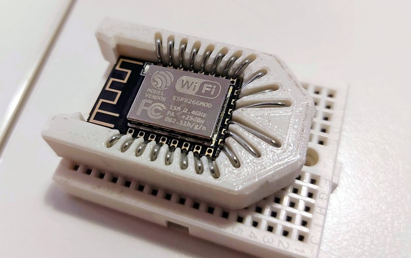
It all started with wanting to program an ESP-12 variant of an ESP8266 module without involving any solder. Displeased with all the socket offerings on Thingiverse, [tweeto] set out to design their own breadboard-friendly snap-fit socket.
 This certainly looks like a handy solution. All you have to do is print the thing, add all the wires, and stick your ESP in there. Even that wire is easy to find; [tweeto] used 0.8 mm paper clips which are sturdy, conductive, and haunting the darkest corners of every desk drawer. They’re also a little bit on the thick side, so [tweeto] plans to test out 0.6mm copper wire in the future.
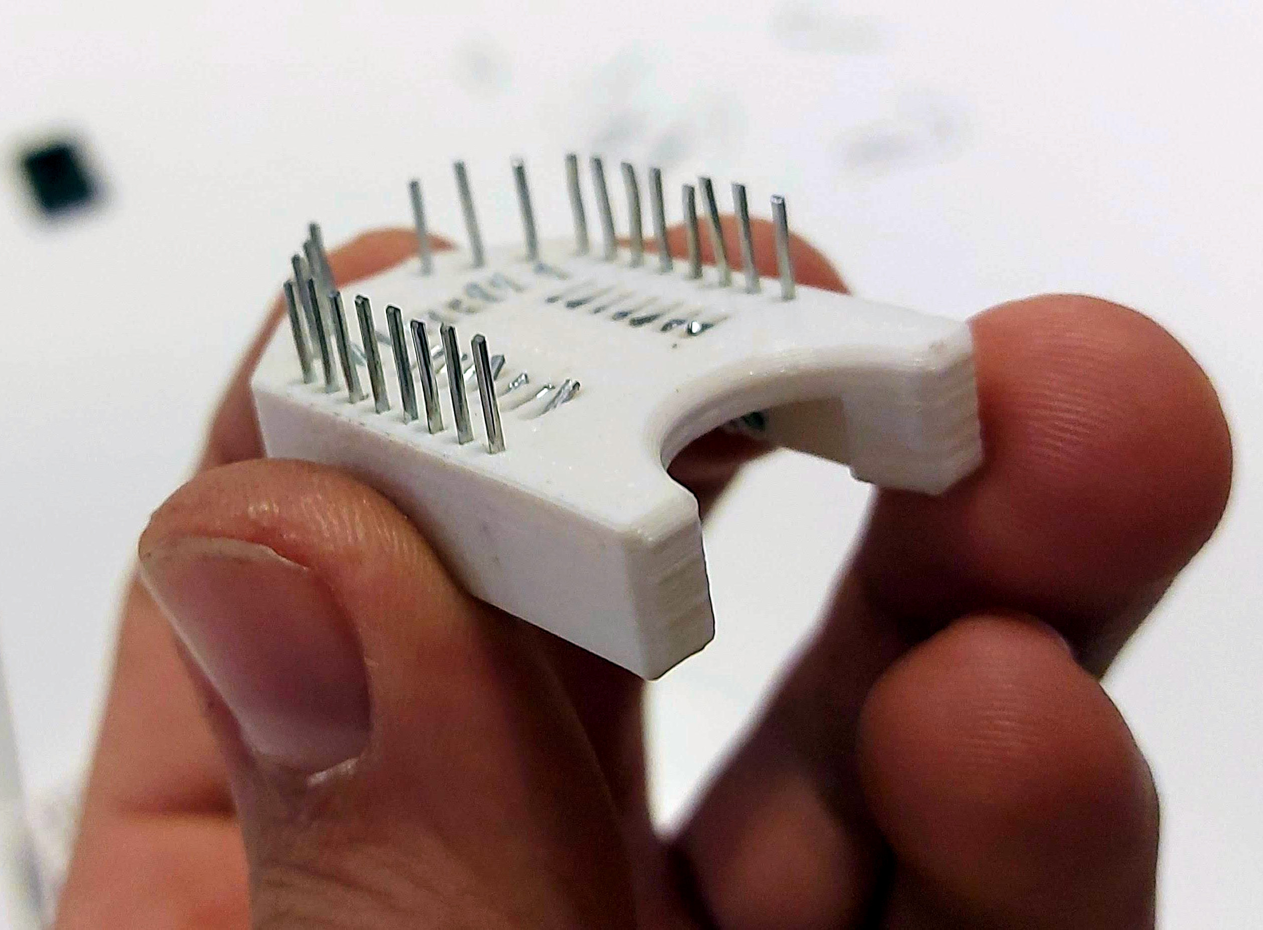
The challenge with this type of print is to design something that will stand up to repeated breadboardings without losing legs or falling apart. [tweeto]’s elegant solution is a tiny groove for each wire in the bottom of the socket — it keeps the wire in place by countering the play caused by inserting it into and removing it from a breadboard. See how [tweeto] bends the paper clips in the short video after the break.
There’s more than one way to use 3D printing to your circuit-building advantage, even in permanent circuits — just take a look at this PCB-free Arduboy.


This is very clever, I can imagine making similar sockets for other devices.
Very nice, I use a lot of these modules this could be useful.
I would though simplify the design as from experience I found the end pins are all used by the onboard flash chip and are therefore not available.
end pins are typically int, clk, miso, mosi and are commonly used?
I thought the end pins were also used for USB for some reason.
The 8266 has 2 hardware SPI- the one typically used for Flash can be used by the user for normal SPI in “overlapped” mode, which I personally use when projects require SPI, freeing up the other SPI pins for whatever GPIO I want – granted only 3 extra pins, but that’s still an 18% increase in available IO. So when breadboarding I only use boards that break these out such as the Lolin
if you can get the pitch down to single strands of copper, imagine the dip sockets you could make?
Cut the shape of your component out of a sheet of wood or plastic, cut around it to leave say a ten mm border. Wrap enameled copper wire around in a tight single layer solenoid. Add some super glue to the top face, to hold it all in place. Cut a long the bottom face all the way around and splay out all the ends. Now sand or burn off the enamel from the inner face. Insert your comment. Universal fit, at least one of the wires will go to the pin you want. You can also so a big bundle of copper wire, set it in apoxy and sand the end flat. Clamp it in a block and have a sheet clamp down on top to interface with any size or pitch ball array chip.
not bad, i typically just use left over leads from resistors and such and solder them to the esp module then insert it into a bread board.
In EEvblog #592 (mailbag) a similar system (with gold plated testpoint wires) was used with an “eRIC4”, “easy radio”
Neat concept, and well done, but for V2 I’d rotate it 90 degrees so that it takes up less space on the bread board.
If it’s rotated 90 degrees, all of the pins down each side will be connected to each other (that’s how breadboards work) and you’d have nowhere to plug in any wires. Suggest buying a larger breadboard :)
Perhaps it is the ‘other’ 90 degrees.
Reference the Enterprise/Reliant battle.
Have another think about that with regard to how the sockets on breadboards are usually wired. I think you’ll find that he’s current orientation is the most optimal.
Maybe they mean flip up vertically
I made something similar few months ago but obiouvsly no one knows: https://www.ebay.it/itm/333710050986
Very nice! But limited to programming use, since only 8 pins out of 22 are connected with pogo pins. Can’t be used for debugging or as a test point bed.
It has serial communication for debug
I’m currently seeking a solution for WROOM-02 and WROOM-32 modules, with all pins available for debugging/test purposes.
Soldering/desoldering a module is painful because of the big square pad underneath, so existing PCB adapters are not usable.
Soldering individual wires to each and every pins is painful (but desoldering easier). So i thought that using pin headers would be easier for soldering (but a little less for desoldering).
And i don’t have a 3D printer nor skills to design and print such a clever adapter.
For WROOM-32, pin pitch is 1.27mm/0.050”. I was hoping to find some already made cables (or suitable components to make one) to convert to 1.27 to 2.54 pitch, but found no solution.
So i’ve bought some 1.27mm pitch single row pin headers and sockets, and i was thinking to use socket to make a 1.27 to 2.54mm adapter, by bending odd pins 90° right and even pins 90° left in order to be able to solder them to 2.54mm perfboard pieces, were i can then solder 2.54 sockets or headers. And then by cutting holes for headers in some plastic or wood board, and plug headers in sockets, i hope i will be able to just “plug” module in-between them without soldering. I’ve not tried yet, so don’t know if it will work.
For WROOM-02, pin pitch is 1.5mm, so not corresponding to any pin headers/sockets :-( So i guess i will have to stay with individual wires…
Except is some Hackaday reader have some better and clever ideas?
Is not clear to me why you don’t use a dev board with 2.54″ headers exposed, the ones you find on alexpress or ebay.
You can develop your software with a circuit on breadboard or wired with jumpers and when it’s finished flash it on module before soldering it on your final board.
Because i need to reverse an existing device, with a WROOM-32 module with its flash content encrypted (so can’t be copied and reflashed on a new module).
So i want to desolder the existing module once, mounting it to a solderless adapter, probe every signals while using it, and finally, since i don’t want to sacrifice the device, be able to resolder the original module in place or maybe replace it with a new one with my own firmware.
They already make things like this, here is an example for the ESP32.
https://www.amazon.com/ESP-WROOM-32-Development-Fixture-Wireless-Transceiver/dp/B083Q8GR99/ref=pd_day0_147_31?_encoding=UTF8&pd_rd_i=B083Q8GR99&pd_rd_r=6881e85e-464c-4686-81f6-b49c07b2b06a&pd_rd_w=Vzfk4&pd_rd_wg=RpAOA&pf_rd_p=ecf748b5-e796-4a0d-9a46-406a973ba8da&pf_rd_r=YTRKMP11B0PWYSHR8R56&psc=1&refRID=YTRKMP11B0PWYSHR8R56
Wow, i want to by it) I am working with bare microchips and this thing will really help me with debugging
i have tried to do things like this, especially for PLCC, over the years…and i’ve always failed. i can’t help but feel that the reason this succeeded is that it’s really unnecessary? it looks to me like the esp board they used has 100mil pitch holes already, why not just stick regular pins in those holes and solder directly to the board?
I’d imagine it’s semi production, not prototyping. Flash code to board, then surface mount it, otherwise pins would be acceptable.
Clever! The same solution would also nicely work with the newer Arduino Nanos which use the castellated pads as well.
I also had to design one for an esp8266 programmer, but all of the options in thingiverse (and this one too) were way too chunky for no real reason. anyhow, the back pins shouldn’t really be broken out as they’re used internally for the flash memory
Back pins can be shared for user SPI if you use SPI, freeing up the other SPI pins for more GPIO