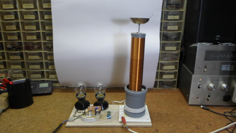
Tesla Coils are a favourite here at Hackaday – just try searching through the archives, and see the number of results you get for all types of cool projects. [mircemk] adds to this list with his Extremely simple Tesla Coil with only 3 Components. But Be Warned — most Tesla coil designs can be dangerous and ought to be handled with care — and this one particularly so. It connects directly to the 220 V utility supply. If you touch any exposed, conductive part on the primary side, “Not only will it kill You, it will hurt the whole time you’re dying”. Making sure there is an ELCB in the supply line will ensure such an eventuality does not happen.
No prizes for guessing that the circuit is straight forward. It can be built with parts lying around the typical hacker den. Since the coil runs directly off 220 V, [mircemk] uses a pair of fluorescent lamp ballasts (chokes) to limit current flow. And if ballasts are hard to come by, you can use incandescent filament lamps instead. The function of the “spark gap” is done by either a modified door bell or a 220 V relay. This repeatedly charges the capacitor and connects it across the primary coil, setting up the resonant current flow between them. The rest of the parts are what you would expect to see in any Tesla coil. A high voltage rating capacitor and a few turns of heavy gauge copper wire form the primary LC oscillator tank circuit, while the secondary is about 1000 turns of thinner copper wire. Depending on the exact gauge of wires used, number of turns and the diameter of the coils, you may need to experiment with the value of the capacitor to obtain the most electrifying output.
If you have to look for one advantage of such a circuit, it’s that there is not much that can fail in terms of components, other than the doorbell / relay, making it a very robust, long lasting solution. If you’d rather build something less dangerous, do check out the huge collection of Tesla Coil projects that we have featured over the years.


ok, so who else had to look up ELCB to find out that you use them all the time but now how they are typically referred to in your area?
Very nice build. Appears to have a more stable output than the last one I seen using a similar setup. Probably because of the current limiting, also not melting the relay terminals.
Same here. Had always known them as RCDs. The more you know..
Excerpting from [1]: “An Earth-leakage circuit breaker (ELCB) is a safety device used in electrical installations with high Earth impedance to prevent shock. It detects small stray voltages on the metal enclosures of electrical equipment, and interrupts the circuit if a dangerous voltage is detected. Once widely used, more recent installations instead use residual-current devices (RCDs, RCCBs or GFCIs) which instead detect leakage current directly.”
In my universe we call these Ground Fault Circuit Interrupters (GFCI’s) or more simply Ground Fault Interrupters (GFI’s).
References:
1. Earth leakage circuit breaker – Wikipedia
https://en.wikipedia.org/wiki/Earth_leakage_circuit_breaker
An ELCB is definitely NOT what’s wanted here. From the Wikipedia article you linked to: “A voltage-sensing ELCB does not sense fault currents from live to any other Earthed body.” And from https://cselectric.co.in/blog/difference-mcb-mccb-rccb-elcb/ :”ELCB is working based on Earth leakage current. These devices measured the voltage on the earth conductor; if this voltage was not zero this indicated a current leakage to earth.” Because an ELCB detects voltage, it won’t trip based only on a current differential between Line and Neutral; so it doesn’t protect a person from current between Line and a ground connection other than the one tied into the panel. What’s needed is a GFCI or an RCCB – probably the former, as from what I can see so far RCCB’s have much higher trip currents than GFCI’s.
Um, actually, a GFCI wouldn’t help, either. A GFCI passes both the hot and neutral conductors through a bifilar-wound relay, which senses only the difference in current between what is going out and what is coming back. In principle, any current to ground in the circuit is bypassing the proper return path, so the current through the hot side is higher than the return side by the amount of the leakage. But because the secondary of the Tesla coil described here is isolated from the primary, and also because one side of that secondary is GROUNDED, current through you to ground only completes the secondary circuit while the current through the primary side all returns on the neutral.
By the way, the same thing applies when troubleshooting hot-chassis circuits by using an isolation transformer plugged into a GFCI-equipped outlet. The isolation transformer isolates any fault current in the device under test from the GFCI.
A Tesla coil is operates at radio frequencies, so the operation of any GFCI might be outside of it’s capability, or create nuisance trips. Certainly new homes with the mandated Arc-Fault (AFCI) breakers may be problematic. These already nuisance trip for many reasons, including HAM radio.
Over here we call them FID, I have no idea what is it shortcut for.
It’s good that it’s not a AFCI. These cost an order of magnitude more than a CB and are mandated more and more making a “fusebox” cost multi-kilobucks. That term is an arc fault circuit interrupter. Old style thermostats in irons, heaters, etc. and line powered Tesla coils will trip one. I have a import “Dremel” tool that rips up the AM band with static it’d likely trip one too.
Hooks up to 220 ??? Might as well use….1.21 jigawatts……feed it to a huge superconductor to create a stable worm ho!e for travel……” you know…..round ring…flushes sideways..” – Jack O’Neal SG1
Classic Tesla coils use neon sign transformers that raise the voltage to about 6kV, typically at currents that would kill you immediately, feed that to DIY foil capacitor (or, on rare occasions to Leyden jar), and then via spark gap to primary coil. This version here skips a neon transformer and replaces the spark gap with basically a relay in self-breaking configuration.
Thermionic valve variants sometimes (usually based on GU81) are usually powered from a step-up transformers as they require about 1-2kV to work with decent power. DRSSTCs are also often powered directly from the grid…
I’ve once seen an OTG (off the grid (directly powered via a rectifying bridge)) thermionic valve headphone amplifier that had absolutely no galvanic separation at any point. Not even a speaker transformer. And it had no fuses, because fuses “degrade sound quality”, according to som audio-voodoo experts…
I have seen a tube based OTL headphone amplifier for electrostatic headphones without galvanic separation. Can’t find the webpage anymore but that thing was closer to an electric chair than a headphone amplifier. http://quadesl.com/diyaudio/tube_headphone_amp.jpg this “normal” OTL headphone amp is also treacherous because at first sight it looks okay, until you realize the B+ comes straight from mains as that transformer only supplies the heaters… not sure if that IEC socket is a fused one either
It’s possible that this puts out an illegal and annoying amount of RF. If you don’t want to have hams tracking you down and bringing FCC complaints, make sure the tank frequency _and_its_harmonics_ do not land on a ham and (or any other HF band where someone would care, for that matter). Add both capacitors and inductors to filter the power line (which will otherwise be a transmitting antenna). Or better, find a design without a wideband noise source like a spark gap.
Consider that there are reasons that spark gaps are not common components these days.
It’s not just the spark gap that’s the problem. The problem is that “damped oscillations” are inherently wide band signals. If you kick a passive LC circuit it will initially ring at its resonant frequency, but as the amplitude dies down, the frequency also drops off.
The way simple Tesla coils work is to repeatedly charge the primary capacitor, and then dump that energy into the primary LC circuit. Large diameter conductors are used in the primary to minimize resistance there, which leads to higher Q, and thereby longer lasting oscillations, but inevitably those oscillations die out, i.e., are damped out, by that resistance. The whole process repeats at line frequency as each new cycle of the mains recharges the primary cap, but the individual ‘high frequency’ pulses are damped oscillations.
When allowed to radiate, this clobbers large swaths of the spectrum. In the US, I believe the FCC specifically bans the intentional radiation of damped oscillations.
Yes as I understand it, and please correct me if I am wrong, but the FCC was set up to control and then ban spark gap transmitters.
Please don’t fire this up in my town when I’m trying to:
Watch TV
Needing a police or fireman who would need radio communications
Connecting to WiFi
Trying to talk to someone in another country on amateur radio.
Actually EMI generated by these small Tesla coils is quite limited. Especially considering that secondary coil and torus/ball/metal electrode on top form a series LC tuned circuit. You need a specially-wound inductor in such setups to generate HF frequencies, and serious amount of power to have any range…
The main thing going for you with a device like this is that it’s not a very effective as a transmitting antenna.
If your device is optimized for a certain frequency, that’s just where the peak output will occur. Simple TC designs using damped oscillation will puke RF all up and down the band. Anyone nearby tuned anywhere near your nominal TC frequency is going to hear a horrid buzzing at 2x your mains frequency, as each damped pulse sweeps past their operating frequency.
Note that ‘electronic’ TC designs, that drive the primary with an actual semiconductors (or vacuum tubes, if that’s your thing), won’t have this problem, as the amplitude of the device is relatively steady, keeping the device ‘on pitch’
Yes, and a coil of less than 400 microHenries will generate no corona effects, but will great RF interference in AM Superheterodyne Receiver
Its a cross over between a Ruhmkorff-inductor and a tesla coil. Perfect to spray the whole rf spectrum with noise.
You can do that with just a Ford Ignition Coil, a DPDT relay, and an aerial
Build safer Tesla coils using primary batteries only! For it all depends on what magnitude of effects you are looking for.
If you want or need Tesla coils that generate only 4KV or less, then just use batteries and a simple xsistorized exciter crkt. SAFER!