Draining a battery is easy. Just put a load across the terminals, maybe an incandescent bulb or a beefy power resistor, and wait. What’s quite a bit trickier is doing so safely. Put too large a load on, or leave it connected for longer than necessary, and you can end up doing damage to the cell. Not convinced he’d always remember to pull the battery out of his jury-rigged discharger at the opportune moment, [Jasper Sikken] decided to come up with a simple tool that could automatically handle the process with the cold and calculating precision of silicon.
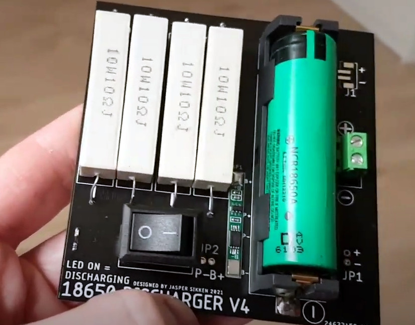
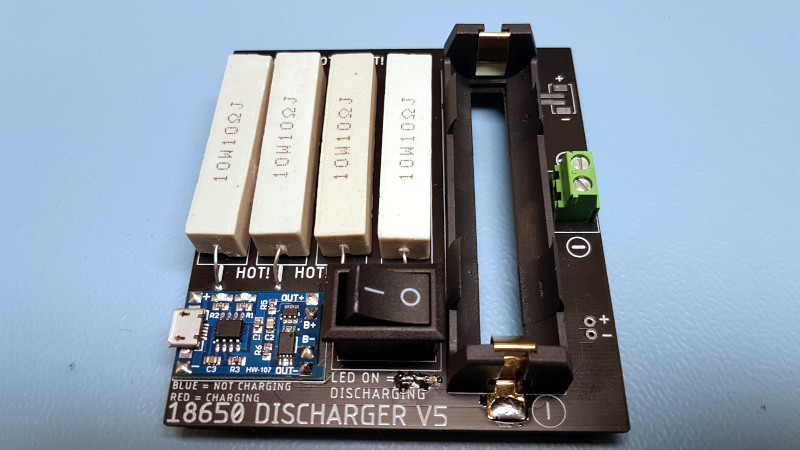
At a glance we can see the major components you’d expect in a discharger: a fairly simple PCB, four ceramic power resistors, a holder for a single 18650 cell, and a rocker switch to connect it all together. But wait, what’s that a TP4056 charging module doing in there?
While its presence technically makes this device a battery charger, [Jasper] is actually using it for the onboard protection IC. With the charging module between the cell and the power resistors, it will cut the connection when the voltage drops to 2.4 V. Oh yeah, and it can charge the battery back up if you connect up a USB cable.
[Jasper] says his little tool works great, with the resistor array putting just enough load on the battery to pull it down quickly without getting so hot that they’re dangerous to have exposed. He estimates the BOM for this gadget runs around $2 USD, and is considering offering it as a kit on Tindie in the near future.
If you’re looking for something a bit more advanced, [Jasper] built a programmable load a few years back that can discharge batteries and test power supplies all while logging the data to your computer for later analysis.


Nice build
I’d buy one
https://www.tindie.com/products/jaspersikken/18650-discharger/
No this I would be interested in as I seem to be collecting more 18650 batteries and projects.
If this is discharging for storage with the intent to reuse, cutting off all the way down at 2.4v is not a good idea.
Ideally you target around 3.4-3.6v – well above the point where you risk damage to the battery, well below the point where the battery’s capacity degrades more rapidly.
According to many Li-ion battery datasheets it is safe to discharge to 2.5V and capacity of many li-ion cells is specified between 4.2V and 2.5V. However below 3.0V the remaining capacity is neglectible so most applications stop at 3.0V. However in this case as soon as it hits 2.45V the load is released and the voltage quickly recovers to 2.85V so I believe the damage is little.
It is normally safe to discharge them in use, but not for (prolonged) storage. Although self discharge in LiIon batteries is tiny, any self discharge brings them down, when they are already at the lowest safe state of charge.
Yup. There’s a difference between “safe for short term” and “good for the battery long term”
Both extreme ends of the discharge curve are undesirable. 40-60% BSOC is ideal for storage.
For example while lithium self discharge is very low, if you discharge it to the safe limit, you risk self-discharging into the damage zone. Meanwhile if you discharge to 40-60% for storage, it’ll be a LONG time before it self-discharges to a point where damage may occur.
Can someone help explain the reason behind this project?
Typically when we cycle 18650 cells it is to measure their capacity, which this discharger doesn’t do.
If the purpose is to discharge a cell for storage, it really should stop the discharge at 3.6-3.7v.
If the purpose is to discharge a cell for disposal, then why worry about stopping the discharge on the low end at all?
So, what is the purpose of discharging a cell all the way down to the point of low voltage cutoff?
According to the linked .io page, they were designing a battery charger, and needed to drain their batteries so they could test the charger.
Oh ok. I guess that kinda makes sense then. Still seems like an edge case that not many people will run across. Wonder how many will sell and what other people would actually want them for?
So-o-o-o-o-o-o… 6 diodes and a light bulb, done.
Yes. Or a zener. I can’t see anything simpler. I have a couple of these type loads but have not done the testing I had planned on. https://www.banggood.com/35W-Constant-Current-Double-Adjustable-Electronic-Load-QC2_03_0-Trigger-Quick-Voltage-USB-Tester-p-1194871.html?cur_warehouse=CN&rmmds=search
A couple of things to consider:
– Putting a high heat sorce next to a Lithium cell isn’t the smartest thing to do. Fire hazzard anyone?
– Might want too raise those resistors above the PCB, put some space between them and have some slots/hole in te PCB to help to cool them. Could stagger the heights between the old/even rows to increase spacing without affectng board space and/or adding a fan.
– Like others say, don’t drain the battery al the way down. May be a low voltage cutoff. e.g. a power supply supervisor driving a MOSFET as a switch.
“With the charging module between the cell and the power resistors, it will cut the connection when the voltage drops to 2.4 V. “
From the source: “The 2.5 Ohms load is disconnected at 2.54V and reconnects at 2.87V.”
Did you actually read the post, or are you commenting based on just the picture?
If you’re going to that trouble, replace the TP4056 with a ATTiny or ATMega board (Promini or Nano would be my choice for convenience) and a display of some description, do your cut-off in software, and measure the capacity on the way down.
If you’re going to use an ATTiny, you need extra components to handle the current and regulation, so you aren’t making any improvements.
No. This is intended as a safety measure. So this is well done in hardware. Although a typical protection IC (WD01, DW01?)and dual MOSFET would be enough.
That’s getting a bit dicey for a low voltage just to test charging. I don’t think all the cells rate down to 2.4v for a safe discharge voltage. I could be wrong but my memory says 2.7v for the last cells I was working on and the Internet writ large quotes “2.0v to 3.0v depending on specification sheet”.
Anyone known the chemistry nuances on that for short time between discharge and recharging across a few different cells?
The voltage under load is lower because of the internal resistance, so the threshold under load needs to be lower than the threshold without load. In the source you can see the circuit has hysteresis between 2.54 Volts and 2.87 Volts. When the load gets disconnected, the cell output voltage jumps up immediately – the cell isn’t truly discharged below about 2.8 Volts.
There’s really no reason to go below 3.0 volts.
With like two more cheap/off the shelf components you could also measure the capacity and have constant current.
https://hackaday.io/project/163626-minimalist-li-ion-dischargercapacity-meter
that turns out not be the case.
I use a lot of panasonics NCR18650B based ones, and panasonic says (and I have tested) 2.5V for the NNP ones ie https://eu.industrial.panasonic.com/sites/default/pidseu/files/downloads/files/panasonic_li-ion_handbook.pdf
– they have a hard cut-off at 2.3V
Yes, there are recommendation as to charging them from 2.5v, but that isn’t hard.
Why do you want to go down lower than 3V? Look at the power curve
https://www.batteryspace.com/prod-specs/NCR18650B.pdf
There is a significant amount of energy below 3v.
In practical terms, and after a lot of testing, I take my down to 2.7v while being used. And no, I don’t store them at that!
>There is a significant amount of energy below 3v.
At low temperatures and high discharge rates. Otherwise you gain <5% and significantly reduce the number of cycles you are able to pull out of the battery.
which why I have tested it a fair bit. And it helps to use genuine Panasonic batteries! I finally found a source in Aus that had the real ones – and by the way, it is easy to tell – you test them :-) and they preform way better than anything else you have prev tried.. :-)
I don’t buy anything else now, as they are much better than the cheaper crap on the internet..
Want to share the source? Good vendors deserve getting more business.
Much handier would be one with two displays (battery V and target discharge V), a couple of up/down arrow buttons so I can set the discharge voltage dynamically, and a big red go button.
Speaking of 18650s, anyone have a reliable US source for cells that aren’t counterfeit Chicom cr*p?