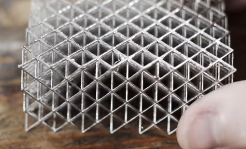
Resin 3D printers have a significant advantage over filament printers in that they are able to print smaller parts with more fine detail. The main downside is that the resin parts aren’t typically as strong or durable as their filament counterparts. For this reason they’re often used more for small models than for working parts, but [Breaking Taps] wanted to try and improve on the strength of these builds buy adding metal to them through electroplating.
Both copper and nickel coatings are used for these test setups, each with different effects to the resin prints. The nickel adds a dramatic amount of stiffness and the copper seems to increase the amount of strain that the resin part can tolerate — although [Breaking Taps] discusses some issues with this result.
While the results of electroplating resin are encouraging, he notes that it is a cumbersome process. It’s a multi-step ordeal to paint the resin with a special paint which helps the metal to adhere, and then electroplate it. It’s also difficult to ensure an even coating of metal on more complex prints than on the simpler samples he uses in this video.
After everything is said and done, however, if a working part needs to be smaller than a filament printer can produce or needs finer detail, this is a pretty handy way of adding more strength or stiffness to these parts. There’s still some investigating to be done, though, as electroplated filament prints are difficult to test with his setup, but it does show promise. Perhaps one day we’ll be able to print with this amount of precision using metal directly rather than coating plastic with it.
Thanks to [smellsofbikes] for the tip!


Now, THIS, this is a hack. You win.
To elaborate: to demur about the imperfections of version 1 is just step 1 of version 2. Which we’ve kind of been talking about, lately. Seeing the possibilities in the ho-hum process of FDM, and taking the next step? That’s what humans do. I eagerly await version 2.
Nice idea! (that’s actually in use in several industries already, BUT great to see it done in somebody’s shed/garage!)
Have you looked at electroless nickel plating? It should provide a more even coating thickness throughout.
Kinda hard to start it (ya know, plastic wont reduce the nickel), but is a good one once an autocatalytic substrate has been deposited. Maybe we can embed powder metal particles on the surface by tossing metal powder on the part, then blasting it with with a short duration high intensity heat, maybe from a IR source (if the resin result on a thermoplastic or a polymer that would behave alike for the purpose I presented).
I think it would result in greater overall strength, since the metalic substrate would look kinda like a open cell sponge on the interface, increasing contact area, and interfacig directly with the polymer
Make the resin conductive!
Any hackaday reader knows all the conductive ink/additives stuff and has an idea exactly what to mix in the resin to make this happen? Maybe adding super-fine copper powder to the resin?
Carbon powder seems like it would be the finest additive, no?
In any event, a thin copper plating is recommended as a “bright dip” layer for plating other materials, like silver or gold.
I played with home electroplating as a teen. It was fun, but a lot of work, and you’ve got chemicals to properly dispose of. As I recall, you need a fairly strong HCl acid for the electrolyte.
Copper powder will gel / crosslink the resin unfortunately.
Check Tom’s last week video on his experiment with mixing exactly that.. He says it makes barely conductive.. But to get a base layer of electroplating to start may be enough..
https://youtu.be/BQWV12kIy6E
A couple of comments about electro plating. To plate metal onto an object you induce a current flow and electrons at the surface of the object reduce the metal ions to solid metal. Generally a metal electrode is present which dissolves and goes into ionic solution while the ions then plate onto the other electrode. Areas where the two electrodes are closest cause higher current flow which leads to thicker plates in that area. Crevices are areas of low current flow which leads to thin plates. The ability to plate uniformly is helped by shaping the dissolving electrode to fit. Another common way to help crevice plating is to use a chelating agent like cynanide which explains why plating is expense due to the hazards and regulations to safely handle it.
In electroless plating, you get the electrons to form the plate metal by dissolving the base surface. The base metal gives up its electrons and becomes ionic ie soluable while those electrons are picked up by the metal in the plating solution and which reduces to metal. In practice, electroless plating is not great because it’s like building your house on the shifting sands as my electrochem instructor said. Copper is a great metal for plating since it tends to cover over pin holes and gives fairly smooth, well adhered, easily plated surface. For high bumper plating, copper is plated first to get a base layer, followed by nickel then Chrome. It would have been interesting to see if copper/nickel would have helped thermal adhesive issues mentioned in the video.
I remember reading about this a couple of years back. It would be great for creating RF and microwave lenses. Imagine an ultrasonic spotlight but for wifi or crowd control. Some serious implications, for a technology that could be within reach of anyone with a fish tank full of gel and a couple of laser galvos.
Anyone have a good formula for conductive paint for parts? I tried this years ago and never got much of anywhere. I bought super fine copper powder and tried graphite but didn’t really get anywhere.
I’ve seen a post somewhere about carbon fiber. Chopped CF will unravel on organic solvents, and the fibers are very good conductors. The post instructed how to make conductive rubber/silicon. It would make a bad paint, as you can forget even coverage, but is still useful for the right applications .
It could be interesting if the resin could be made conductive, then you wouldn’t need to paint or dip it. Perhaps the parts could be printed in wax and then the wax could be removed to create an aerogel like tubular frame. Still pretty strong but much lighter. Imagine this was coated in titanium and the lattice was made finer or perhaps formed from curved sheets.
What if you instead used investment casting to replace the PLA lattice structure with molten aluminum?
Pour plaster over the entire lattice mold, pour molten aluminum into the lattice structure?
You could also use it to reinforce concrete, but aluminum typically reacts with concrete so if you electroplated the aluminum in something non-reactive you’d have a pretty solid block of concrete and aluminum.
I think most 3D part printing should be for the creation of moulds, ceramic, metal, and resins are all viable materials for moulds.
I see so much Etsy type stuff produced by direct printing 3D, when they would be quicker and just as good to do via mould processes.
Be careful with nickel plated jewelry, there is a skin sensitivity to nickel which can cause a smaller percentage of people to breakout
Electrocoating and plating has been done by jewelry makers for a long time. I’d look there for inspiration.
^^^ This!
That is what I was doing as a teenager. I got my information from the Audels books on engineering and manufacturing.
It’s also been done for generations for chrome plating baby shoes, sports trophies, keepsakes and other ephemera.
Get a layer of copper on to plastic, leather, wax, fibreglass etc first, then the chrome platng sticks to that.
1) Print detailed plastic part, plate with metal to get desired finish.
2) Invest metal plated part in plaster, bake out the plastic.
3) Inject molten metal into hollow metal shell in plaster investment.
D) Profit from superb surface finish and solid metal parts.
Nickel plating could handle some grades of steel, copper plating could hold some types of aluminum or ‘casting metal’.
Check out Thought Emporium’s video on the sputter magnetron. Could work to get the initial layer of metal onto the onject
Vacuum vapor deposition (with aluminium) – pretty standard way of making metalized plastic.
How good a vacuum is needed for this?
They seem to need very high vaccum – need diffusion pump. The set up is not cheap.
There are a couple of guys on youtube using it to make conductive thin film or coat telescope lens.
On the industrial scale, they make car parts etc.
It’s kinda, how good a finish do you want? High precision optical first surface mirrors you want 10^-6 Torr, a’ight mirrors 10^-5, a little frosty looking but still smooth is happening by 10 ^-3 and it gets grainy looking at a worse vacuum than that.
I have seen home fridge compressors repurposed to do vacuum duty. It looked pretty strong to me at the time. Hit the search engine…
Forgive me if I’m missing something out of ignorance of electroplating (I’ve not tried it yet), but I was thinking about this process and had an idea. What if someone were to put a stable layer down on the outside of some water soluble resin, then drilled a hole in it, flushed out the soluble material, coated the outside with a material to prevent further plating (to preserve size and detail, then plated it from the inside to make it solid? I can imagine some cavities if not designed and drilled properly, but if done just right and with appropriate parts I can imagine it is possible. Maybe the amount of copper sulfate (or whatever you’re using) would be prohibitively expensive?
It’s simple enough in principle, it should work. There’s some risk that the area around the entry hole would plate fastest, and would close off the opening well before the rest of the cavity is filled, but that can be fixed by poking the donor electrode down in the hole, so it plates from the bottom up.
Copper sulfate is not very expensive, and I don’t think it gets consumed in the process. The copper anode (the electrode connected to the positive current supply) is what supplies the material that plates onto the cathode (piece being plated).
Plating is often used on printed circuit boards to build up the thickness of the conductors, so plating large amounts of copper isn’t really a big challenge.
But an easier way of doing this would be instead of just coating the outside, immersing it in plaster so that the thin walls are well supported. Then you can drill that hole and inject molten metal into it. Though I’m not entirely sure this would be an improvement over ordinary investment casting, since if the original plating melted, it might take on the texture of the plaster rather than retaining its metallic gloss.
Thanks for your insight. I thought about the hole closing up, and I supposed you could just re-drill it when needed. I had forgotten that the copper sulfate is replenished by the anode. I might give this a try sometime when I find a need.
Electric run time meters are made that look kind of like a mercury thermometer – they are a glass tube filled with mercury, with an electrolyte filled gap. A fixed current is passed through this, and over time, mercury plates from the anode to the cathode, so the position of the gap moves at a rate proportional to the current. https://www.reddit.com/r/ElectricalEngineering/comments/eeczu1/electrochemical_hour_meter_a_drop_of_electrolyte/
For a while, I was seeing a copper version of this, which used a glass tube filled with copper, with the gap filled with copper sulfate. These did not work as well; I saw some that had formed a very thin thread that crossed the gap, shorting it out. That’s a risk with plating: if one spot plates thicker than the rest, it encourages plating faster at that spot, and it grows a spike there, called a dendrite. Happens in batteries, too, since these use similar principles. I’m told this happens when your plating current density is too high, but clearly that wasn’t the issue with these run time meters, that took thousands of hours to plate across the gap for the whole distance.
Anyway, I thought about this because these devices plated copper over a centimeter thick, so that’s an example similar to what you are suggesting.
This reminds me of the metallic micro lattice structures Boeing did back in 2015. Here’s a research paper on it, or just Google metallic micro lattice.
https://iopscience.iop.org/article/10.1088/1361-6528/aa8a3b/meta
This is awsome!!! I work at the plate department at a printed circuit board manufacturer and this is really interesting, thank you. I was trying to convince them to copper plate door handles and touch plates and stuff for the antiviral effects of copper. We have to do cleaning every 2 hours its a pain in the ass. I also considered making a mask insert like your projects thumbnail to filter air threw copper mesh. Thanks very inspiring.