It’s 2021. Everyone and their mother is filming themselves doing stuff, and a lot of it is super cool content. But since most of us have to also work the video capture devices ourselves, it can be difficult to make compelling footage with a single, stationary overhead view, especially when there are a lot of steps involved. A slider rig is a good start, but the ability to move the camera in three dimensions programmatically is really where it’s at.
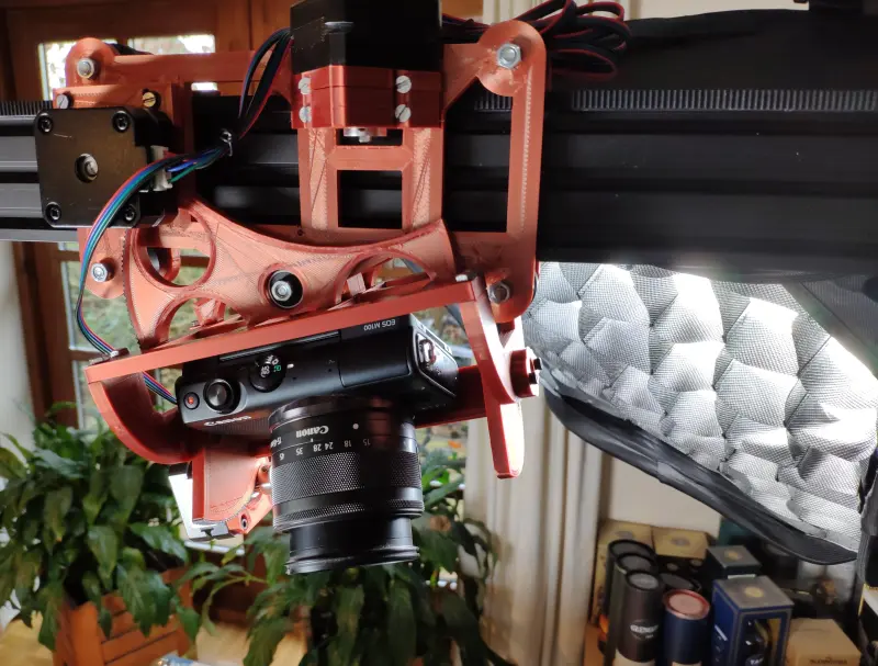
[KronBjorn]’s excellent automated overhead camera assistant runs on an Arduino Mega and is operated by typing commands in the serial monitor. It can pan ±20° from straight down and moves in three axes on NEMA-17 stepper motors. It moves really smoothly, which you can see in the videos after the break. The plastic-minimal design is interesting and reminds us a bit of an ophthalmoscope phoropter — that’s that main rig at the eye doctor. There’s only one thing that would make this better, and that’s a dedicated macro pad.
If you want to build your own, you’re in luck — there’s quite a lot of detail to this project, including a complete BOM, all the STLs, code, and even assembly videos of the 3D-printed parts and the electronics. Slide past the break to check out a couple of brief demo videos.
Not enough room for a setup like this one? Try the pantograph version.


An opthalmascope is a hand held device used for examinig the retina. The big rigs at the eye doctor are the phoropter (with all the lenses, “better A or B”) and the slit lamp which is another eye examining device.
Today I learned…
Thanks, corrected in the text, with a link to Wikipedia that contains an image of a kid in one that looks like it’s out of some sci-fi torture scene from the 60s.
“Better A or B” made me laugh. I thought that was the device’s name!
I love the excellent camerawork on the trainwreck of a tutorial for making soap. You have to know content creators have projects go awry like mine, but to see it all captured with fine detail is a delight.
Nice aperture science core mobility rail!!! Now you can document your testing.
I think I’d prefer to have a joystick over serial commands, but you’re absolutely right – I do need this.
Actually what I’d really like is to snap my fingers at the point at which I’d like the camera to center its frame, then angle my hand such that the camera makes its pan and tilt based on being parallel to the back of the hand.
now that would be cool, opencv, perhaps a depth sensing or simple stereo camera – may need to actually add two cameras as the working one you are aiming is probably set up with more constrained field of view and higher zoom than you want for this detection stuff..
But that would be pretty awesome, and not that impossible to do.
A webcam alongside, feed into the computer … would be a very interesting setup with a ton of possibilities, while still keeping the high-res camera/lens for the final product. Only cost a few bucks, plus software dev.
What does depth get you? Camera already has auto-focus? (Oooh, could you tap into that?)
“What does depth get you?”
For video, setting the focus to where the point of interest is *going* to be: e.g. something new is going to come into frame and you want it in focus as it does so, instead of waiting until it hits wherever the auto-focus is currently looking?
The depth sensing allows for parallax correction – as the extra camera isn’t going to be in exactly the same spot as the primary image sensor (and may not even be mounted on the same part of the arm – extra lump might screw up your existing gimbles freedom of movement or actually get in the way of changing lens on your primary camera etc – so could well just be mounted fixed to some point further back on the arm out the way). Also as your primary camera probably has changeable lens/zoom levels that shift the captured image when changed it would be much easier to ‘correct’ the arm positioning feedback of the system with depth information for what the camera should be targeting.
Also gives you the desired hand pan and tilt control with more vastly better speed and accuracy than sweeping and stacking many seperate 2d image (assuming dense enough depth point field – but even a kinect should manage that from my playing around with mine). Though rather than the back of hand I think using thumb and fingers of both hands like a frame to define the desired field of view, and pan/tilt would be better, and easier for a single extra webcam in conjunction with the primary sensor to lock onto rapidly.
Can also perhaps be used to set the desired focal point, along with using gesture controls, which are more reliable with the concept of depth. With the right camera something like gphoto does let you control your AF lens manually, so you could tap into that.
A very basic webcam mounted close to the normal camera certainly could be useful for many elements and is probably what I’d actually do (though I do have an old CM1 and lots of pi cameras so maybe stereo vision version just because I can, and it uses up a now obsolete bit of kit I have laying around). But a single webcam implementation would be relying on software guesses at times for the advanced features suggested by DougM, so probably rather clunky or slow for those functions.
Ohhh, that is so clean. Nice!
Hats off for making such a smooth motion!
For the commenters, you all need a little more Tucoflyer from scanlime in your life :)
https://www.youtube.com/watch?v=JU6omrP2iFU
I applaud this guy for his efforts, but if you ever want to build something similar, then make at least one change.
The timing belts are stretched straight and then the pulley is then held against it. This is not the proper way to use timing belts. They should always be wrapped partially around the pulley. For full strength you need about 6 to 8 teeth of engagement. This is because the load carrying cords in the timing belts are just a continuous loop, and the rubber (Polyurethane or other plastic) that forms the teeth is just molded onto them.
For very low torque applications you may sort of get away with just a straight stretched belt, but even then it probably introduces uneven movements. If the belt is wrapped around the pulley, then the pulley acts as a perfectly round wheel, (with the diameter of the center of the cords in the timing belt) and the teeth are just filled with rubber (PU, etc)
How would uneven movements be caused? I can think of teeth maybe flexing…anything else? Good point!