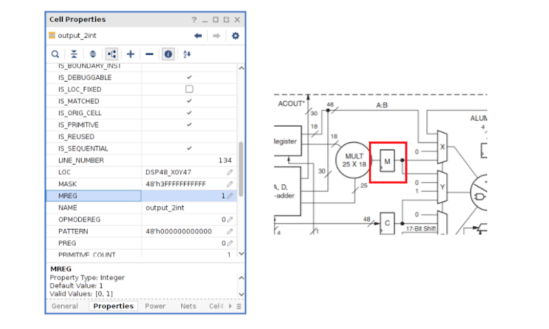
Digital filters are always an interesting topic, and they are especially attractive with FPGAs. [Pabolo] has been working with them in a series of blog posts. The latest covers an 8th order FIR filter in Verilog. He covers some math, which you can find in many places, but he also shows how an implementation maps to DSP slices in a device. Then to reduce the number of slices, he illustrates folding which trades delay time for slice usage.
Folding takes a multi-stage parallel multiplication and breaks it into fewer multiplications done over a longer period of time. This reuses slices to reduce the number required for high-order filters.
By the end, you can see three different implementations of the same filter and it is illustrative how each one uses resources, power, and time. The code is all available on GitHub. The posts focus mostly on Xilinx, although there is also discussion of other DSP block styles.
Mathematically, an FIR filter has no poles which means it is always stable. However, compared to IIR filters which use state information, they require higher filter orders to get similar performance.
If you want to play with FIR filtering, you could do some simulations. Or you could use a spreadsheet.


For the first time for me on hackaday I had no idea what this all is about and had to look up all acronyms except fpga. I feel youg again.
You knew FPGA but not FIR and DSP?
That is wild but a sign of progress in programmable logic I guess.
It’s really worth actually figuring out how to run the DSP yourself rather than inferring it via HDL. I mean, for low performance stuff it’s fine, but if you *really* want to push performance or resource utilization, you *totally* just want to read the DSP’s manual in each one of these chips all the way through. An “intermediary” step is using the Matlab interface and letting the optimization stuff handle it, but, well, that can cost money, and… it’s still not usually quite as good.
For instance, in most cases the DSP is *much faster* than what you’re running the general fabric at (unless you’re *really* pushing things), and on the multiply path they’ve got multiple registers that you can switch between on a clock-by-clock basis. So you may be able to run the DSP at twice the system clock rate, and just have it flip back and forth between two sets of inputs on each half of the clock.
The other *huge* advantage that gets missed often is that FIR filters are frequently *symmetric*, because then they’re linear phase. Which means half the coefficients are identical. How is that helpful? Because there’s a pre-adder, too, so you can group the data with identical coefficients and cut the number of DSPs in half.
So if I imagine an 8th order symmetric FIR running at, say, 100 MHz or so, I can cut the output delay dramatically by running the DSP at twice system clock and grouping the samples. Super-fast FIRs are fun and easy.
Now, fast IIRs, that’s an entirely different nightmare.
Hi Pat,
As you said, you can simply infer the DSP via HDL but the goal of the post was to show ho the synthesizer translate the HDL code into a digital circuit, but the synthesyzer is not smart, and by knowing how it will translate the circuits, you will able to help it to implement what you really have in mind. I mean, that’s not C where an instruction has a asm equivalent, in FPGA there are infinite implementations and all of them have the same behavior.
Regarding the symmetry and the use of twice of frequency, totally agree, it is other optimization that can help you to save resources. You have give me an idea to other post :).
And IIR, they are quite different, but the good news are that you will need a lower order on the IIR filters to have the same attenuation than FIR filter.
Thanks for read!
This is a great post! Btw, the Xilinx FIR Compiler IP (in the vivado IP catalog) uses the same tricks (and more) to efficiently implement a fully parameterized FIR with DSP48\DSP58.
You just stick in the required sample period, and it will fold DSPs if there’s timing budget.
It will also parallelize if you actually have your sample rate faster than your clock rate.
You can configure it in Vivado or in the Matlab-based System Generator tool.
Yeah, having tried it, it’s almost impossible to beat the FIR compiler. Especially over all the use cases it covers. The Xilinx fellas know their stuff.
Hi Daniel,
yes, in fact there are another post where I talk about FIR compiler, but the goal of the post is didactic. Also, the FIR compiler, and the Filter Designer tool from MATLAB have a great disadvantage for me. If you implement the filter, and later you notice that the response is not the desired, maybe because you need more resolution, you have to redesign the filter completely, and this involves to test again the module. In case of parametrize filters, you can change the width of the coefficients, or the internal widths using the same module, saving time in test and verification.
Thanks for read!