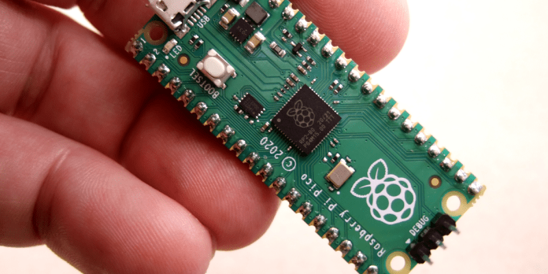
The release of the Raspberry Pi Foundation’s Raspberry Pi Pico board with RP2040 microcontroller has made big waves these past months in the maker community. Many have demonstrated how especially the two Programmable I/O (PIO) state machine peripherals can be used to create DVI video generators and other digital peripherals.
Alongside this excitement, it raises the question of whether any of this will cause any major upheaval for those of us using STM32, SAM and other Cortex-M based MCUs. Would the RP2040 perhaps be a valid option for some of our projects? With the RP2040 being a dual Cortex-M0+ processor MCU, it seems only fair to put it toe to toe with the offerings from one of the current heavyweights in the 32-bit ARM MCU space: ST Microelectronics.
Did the Raspberry Pi Foundation pipsqueak manage to show ST’s engineers how it’s done, or should the former revisit some of their assumptions? And just how hard is it going to be to port low-level code from STM32 to RP2040?
How Hard Could it Be?
Long story short, after the RP2040 caught my eye, I figured it might be interesting to try and port my C++-based STM32 framework to this new MCU. Not so much for the dual Cortex-M0+ cores, though, as I have STM32H7 dual-core (M4 & M7) MCUs lying around which will handily beat the stuffing out of an RP2040 with gobs more I/O to spare. What mostly intrigued me was this state machine peripheral (PIO) in the RP2040 that seemed worthy of a closer look.
Based on my experience with STM32, I figured I could quickly port over some files, create a new ‘RP’ architecture branch in the project and be off to the races. Cortex-M is Cortex-M, right? The usual procedure with a new ARM-based MCU is to get the datasheets, reference manual and the CMSIS device files. After this one can easily adapt the low-level code to use the new peripheral naming & register layout, while core-level devices (SysTick, NVIC, etc.) stay the same.
Perhaps naively, I had put in an order for a Raspberry Pi Pico board before even checking for CMSIS support, or glancing at the reference manual. To my surprise, I found that CMSIS support or even interoperability with the rest of the Cortex-M ecosystem was not yet on the radar. Still, the SVD file for RP2040 MCU is provided in the ‘Pico SDK’, which can be used to generate the device header from. Courtesy of Chris Hockuba’s efforts on bootstrapping CMSIS with the RP2040 I eventually had a working solution together.
This Could be Easier

With an STM32 project, there are a few items required to make a bare-metal project work on a target MCU. These include the start-up code which performs some basic setting up of the environment as well as the vector table for interrupt handlers. There’s also the linker script to ensure that all bits end up at the right memory offset. This is all fairly minimal, with the MCU upon boot loading the firmware image from Flash ROM at the default address.
The first hurdle with the RP2040 is to understand its chained bootloader process. Much like with bootable floppy disks of yore, or a HDD/SSD in a PC, the external QSPI Flash ROM is treated essentially as a potential boot device by the MCU. The first stage bootloader is integrated into the MCU in boot ROM, address 0x0000 0000, which upon boot checks the QSPI interface to try and load 256 bytes from it. This will be checked for a valid CRC32 hash match and assumed to be the second stage bootloader if it matches.
There are a lot of things which this second stage bootloader could do and some which are required. Suffice it to say for now that compared to some famous STM32 clones – such as the GigaDevices I-can’t-believe-it’s-not-a-genuine-STM32 clones – which also use SPI ROMs, this whole process with the RP2040 is not as intuitive, well-documented or transparent as it could be, with plenty of stumbling blocks.
Good Artists Copy
It took me a fair bit of digging around in the RP2040 datasheet and asking around to figure out how the peripheral clock manager in STM32 maps to the RP2040 system architecture. As it turns out, the RP2040’s version is called RESETS and works basically in reverse: you have to unset the reset condition on a block to enable the clock for it. To enable the GPIO clock, you have to toggle bit 8 in RESETS_RESET (PADS_BANK0).
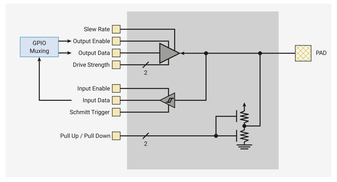
That figured out, I looked at the GPIO peripheral section in the documentation (section 2.19). One thing is immediately apparent: this is completely different from the STM32, AVR, SAM and most other GPIO peripherals I have ever seen.
While most chips have one or two registers per function, and you shift bits into them to activate that function for a particular pin, the RP2040 has a register per pin and you shift bits into a place that dictates the function. It’s a unique choice, and I had to write some custom code to look up the memory address of the control registers for each pin.
After going through all of this effort, surely it will just work, right?
Boot Shenanigans
As mentioned before, the second stage bootloader has to be located at the beginning of the firmware image. Since I figured this had to be some generic code, I simply took the ready-to-use ASM code that got spat out by the official PicoSDK while building the Blinky example. With this added to the RP2040 Nodate port, the Blinky example built without issues.
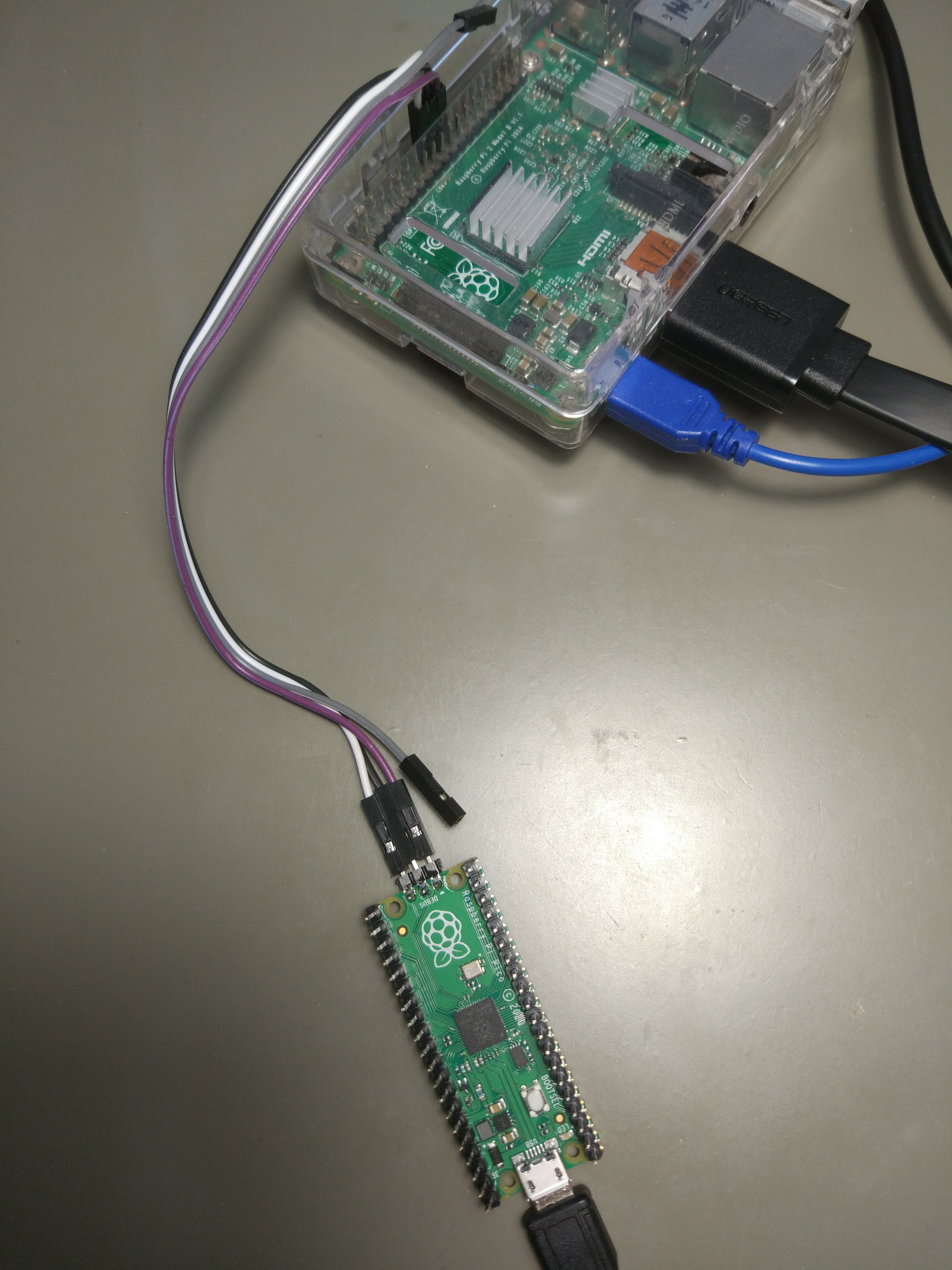
Flashing the resulting ELF binary to the RP2040 was the next challenge, as there is no onboard ST-Link-style SWD adapter on the Raspberry Pi Pico board, and as a dual-core Cortex-M MCU, it requires a multi-drop SWD adapter. So far the only multi-drop SWD adapters which I have are integrated on STM32H7 Nucleo boards. Thus I decided to use the custom OpenOCD fork which was created by the Raspberry Pi Foundation, running it on a Raspberry Pi SBC.
With all that in place, I successfully flashed the firmware to the RP2040 and… got absolutely nothing. From a cursory inspection it appeared that the code never got past the initial boot loader and into the actual firmware in the SPI ROM. Whether this is due to an issue related to the second stage bootloader ASM, something in the experimental RP2040 CMSIS files which I had to borrow from someone else’s efforts, or due to something else entirely is hard to say at this point.
To Be Continued?
After spending quite a few hours on making bare-metal RP2040 work using cobbled together CMSIS and second stage bootloader files, it felt like the right time to take a few steps back and reevaluate. Since my initial evaluation of the RP2040, the CMSIS feature request in the Pico SDK tracker has joyfully been updated with the suggestion that official CMSIS support may be added with the 1.2.0 release of the Pico SDK.
 I think it makes sense for anyone who wants to get intimate with the RP2040 using industry standard tools to wait for this release. Once it drops, I’ll likely end up revisiting first the Nodate Blinky example, and then finally check out the PIO peripheral. Having read up on its two state machine architecture, it seems interesting enough. Not as powerful as a CPLD or FPGA, but still extremely useful.
The single RP2040 ‘datasheet’ (more a reference manual & datasheet mashed together) seems to at times forget that it’s supposed to be covering the MCU, and will veer off into being a Pico SDK tutorial. While useful for those who wish to use the SDK, it’s decidedly less useful to those who are writing their own implementation.
From the convoluted GPIO peripheral, the complicated multi-core boot process, and the added hurdle of having to integrate a second stage bootloader along with a non-transparent external ROM, much of it rather grates. You’re going to want to use the official SDK.
It’s possible that once one gets used to these design choices, it won’t feel as jarring. Or maybe it’s just a question of working the RP2040 into the standard toolchain. Every new MCU is a bit of a learning experience, after all.


i wish maya had gotten to the bottom of why the blinky doesn’t work, so we’d know which deficit was responsible for that stumbling block, and how severe it is…
i’m really disappointed in RPF, now that i finally got a pi. somehow, all these projects on here of people let me miss the point, which is that none of these “pi in a different box” projects actually work very well. i’d heard that it’s relatively closed / proprietary but i didn’t think it was a big deal. i have closed firmware on all my PCs and it’s fine, it “just works.” but the pi is not just closed, it’s in bad taste…the barrier between closed and open is generally completely undocumented, and once i understand it i’m usually astonished at the bad choices which were made and which are now baked into closed-source components. and to top it off, there’s numerous bugs and missing features they just haven’t worked out. closed is only alright if it works.
and the community is little help, generally the remedies people discover, it is like witch magic to them. add this magic undocumented line into /boot/config.txt, and it will work so long as you have a pi 2 or pi 3 and updated the firmware to “the newest version” but it’s been 5 years and if you update to the version after that it’s broken again.
i don’t want to bash the RP2040 without ever trying it myself but it seems from this review that the struggle to get good documentation for the STM32 is nothing compared to the struggle that RP2040 users face.
i’m just mad that they don’t seem to actually understand the community very well. like maya said, when i start on a project i go out looking for all the reference manuals and datasheets, and my uniform experience with RPF is that this is *harder* with their projects than with run of the mill products from regular vendors. i don’t want some sort of one-click installer with an awful buggy limited slow development environment, and i don’t want documentation for that monstrosity. i want documentation of the hardware.
Great post! I agree on everything. You are saying
“when i start on a project i go out looking for all the reference manuals and datasheets”
But it feels like this is not cool enough for people. People don’t want to learn how to actually use their hardware. They just want to plug it in, flash the next python or Arduino code and let it blink some fancy RGB led. While yes, this can be fun, I think the communities should encourage people to learn more about the actual hardware and how stuff is working.
But maybe I am just an old boomer by now
a volatile field discourages virtuosity. It’s something that I find increasingly disappointing the older I get, and the more time I spend developing hardware and software solutions. It’s against our nature.
Ask a carpenter, machinist, art conservator, musician, … what the half-life of their skill set is, and they’ll probably say “I’m never done learning”, whereas with Arduino and co. I feel like I’m never done unlearning and forgetting things.
I never liked Raspberry from the start.
At a time when almost everybody already switched (or was at least considering it) to 64 bits they stuck with 32 OS because it was “good enough for them”. That dragged much old code 10 years into the future and I wonder how much time it has cost (for all their users (and even users of other projects)).
Broadcom has never been anywhere near openness or friendliness and to me it felt like Raspberry was cheaping out from the start with those “left over” multimedia chips they got from Broadcom. Then there is also that camera thing they locked down with some firmware blob, which has probably also caused countless hours of frustration for people who tried to use it on any other processor.
I do like the idea of having an I/O register with all functions together for a single pin, and maybe that statemachine thing is a nifty peripheral, but I am not very interested because I would never use it.
The countless hours needed to get started on a new platform (and I don’t mean arduino blinky leds) is very recognizable for me. Ben there, done that, and it’s not fun.
My first uC was a pic16F84, which I found horrible, as it was only programmable in asm back then, so I quickly changed to Atmel because it came with GCC. That was my first introduction to open source software. Back then C compilers were not so common for uC’s and if it was, it could easily cost several thousands of dollars. Over the years the shine of the Atmel’s wore off because of silly incompatibilities between different chips or even within the same chip. They could not even manage to put two of the same timers in a chip, and had to carefully manage which timer you used for what. they also re-invent a new programming interface every 3 years, and never managed to make a decent programmer for a reasonable price, so I stuck with USBasp, and the chips I could program with it. And it was enough for me for many years. When the cheap TFT’s came from China the AVR uC’s were seriously underpowered, and it became time for something new.
STM32 was popular at that time, and I bought me some Blue Pills (before they lost the race to the bottom. Don’t buy them now anymore! ). Getting them to work was a real pain. But once you’ve managed that, there simply is not much need anymore to look into some other family. It’s a big family and it goes from pretty small chips to big monsters which are in another category in which i’m not interested. But there is plenty of choice. On top of that, STM32 is very popular in chinese products. My Gophert power supply has one. the DPSxxxx series power supplies have them (look at “opendps”) and the brand new Owon XDM1041 multimeter also has one (Almost, it’s fro GigaDevices) for the front panel (This is an extremely hackable benchtop DMM for EUR130!!!) You can also buy PLC’s (starting around EUR20) with an STM32. (Look into FX2 from your local chinese outlet) And such PLC’s are great general purpose development boards for STM32 with hardened I/O. The JYE-tech DSO138 and DSO-Shell also have STM32, and those can also be used as general purpose development boards with an TFT. BigTreeTech makes 3D printer electronics, and they also have some nice TFT’s with an STM32 on the back and the “Nextion” (compatible) displays also have an STM32. So does my JDS6600 function generator.
Recently I bougth about 20 WeAct STM32F411 development boards in small batches (to stay under EUR22 tax limits), and it may take me years before I’ve exhausted their capabilities. I am also very much charmed with the USD3 “ST-Link V2” clones (which also can be repurposed for USB development boards), and I bought a handful of them, just in case one of my others burns out for shorts or other silly mistakes I make. (The latest batch has chips from Apexmicro in them, but I prefer that a lot above one of the 8 “second sources” and then printing STM32 on them. Sellers of such garbage get negative reviews for me, as it is misleading and direct fraud.
So I have no doubt that this latest raspi thing can be used for some projects, but so can any of 10.000’s uC’s from any of the other vendors. I will not even consider a single uC with yet another architecture to use for any of my own projects. Getting to know, and learning to work properly with a new uC family takes a lot of time and effort, and a family of a one is simply not worth it to me. I do have some interest in Risc-V, but there are so many STM32 chips and PCB’s with those chips on them. I can understand people being curious and just wanting to try something new, but I’m not in that category. I need to combine my curiousity with practical projects that I can get going, and for that I need a selection from small uC’s to reasonably big in a single family. That way I can concentrate on the project, instead of learning yet another architecture.
I like the idea of a PLC as a development board.
I’m overwhelmed with google results. Do you have a direct link for a simple (hackable) PLC in your “PLC’s (starting around EUR20) with an STM32. (Look into FX2” criteria?
I think the FX2 is one of Mitsubishi’s range of PLCs. eBay has loads of chinese knock-offs of the FX2 and FX3 ranges. They’re basic green PCBs with screw terminals, so not attempting to look like the Mitsubishi originals, but they give the impression that they’re compatible with Mitsubishi’s GXWorks software. I haven’t bought one, so this is all info I’ve gleamed from the listings.
(Of course, if you’re looking to roll your own code for an STM32, you probably won’t be too concerned about GXWorks and the like.)
Can’t agree more with you. This is why STM32 is so popular in China, but recent 2 years STM32 is so lack, most companies must find other chips, such as GigaDevices which you mentioned, this is also a Chinese local brand. Owon XDM1041 multimeter is only around 800 RMB in China :-)
Well Said…
Documentation is huge problem across the board concerning uC’s, in general. Yes, all the datasheets may be there, but it would take me a better part of a year of testing and debugging to make sense of most of them becaue they are so poorly written. It is so bad that some folks are just putting the high speed, clock-dependent stuff in an fpga because at least you know exactly what that is doing once programmed and just using the uC for high-level processing.
I started out with Kinetis series (old Moto tha got sod a few times) happened to pick unsupported chip for ChibiOS at the steepest part of my learning curve learning Arm and tool chain. I even do some of the porting work. After that, most low level stuff seem easy to me. The chips have great hardware (vs STM32F), but not as well supported in the DIY crowd. The documentation was okay, but… Like they spent a lot of time talking about I2C spec much more than *their implementation* of I2C peripheral. I guess whoever were responsible fr that chapter don’t know enough either and padded the documentation. Took me quite a bit f time to figure that they have 2 levels of pipelines of receive data so I had to signal Stop well ahead. On the other hand, STM8 has a long errata on their I2C part. I wouldn’t figure out how to write my own code without their app note. I had to clean out and use better names for their state machine states.
I have been programming in bare metal mostly on STM32F0, STM8. They are cheap – $0.20 and $0.30 cheap for the batches I got from China. I found no use case for AVR parts. The STM8 has the sane defaults for most registers. e.g. all clocks are enabled until you disable them. With my recent work on trimming down a Russian VUSB stack for my own use, the STM8 covers most of my recent projects. The STM32F103 is older part and not as much fun to use. The documentation is okay.
I have mostly relies on the hardware manuals and only look at the messy vendors supplied code under lots of #ifdef on tricky stuff like switching clocks and waiting for PLL. For me, it is easier to read hardware manual than poorly documented frameworks that doesn’t cover the advanced use case.
Kinetis are probably the best ARM chips out there hands down, but they have such a steep learning curve and poor documentation. Most of the uC have poor documentation because it’s cheaper to support companies buying 10k units with your actual software engineers than have them write docs and tools to support everyone.
I have got an STM32F4 for 2EUR:
http://zoobab.wikidot.com/stm32f401-devboard
The manufacturer had the good idea to fork the open source bootloader, and the CLI flashing tool and the bootloader has been made proprietary. A warm thanks to BSD licensing! Now I have to reverse-engineer this fork to make it “free” again. And I will make it GPLv4 this time.
Why bother wasting time on bootloaders if any STM32 can be programmed with an USD3 ST-Link-V2?
Boot loaders can be useful, especially if the uC itself is inaccessible, but it’s also an easy way to get your software corrupted.
I do not understand this craze for bootloaders. I just plug in a programmer and press a button in my IDE, and it goes through a full compile and program cycle and it always works. with bootloaders you often have to press a button on your target processor (or something else, it changes all the time) to get it in “bootloader mode”. It’s just more of a nuisance then it’s a benefit for me. I don’t have to write or debug bootloader code. I also don’t care if existing bootloader code gets deleted (either accidentally or on purpose to make the Flash more useful.
Also, I think WeAct don’t make the F401 anymore. I very much regret how the very nice “Blue Pill” was demolished by clones and malpractice who label any of 8 different chips and re-label them “stm32”. That is why I only buy the original WeAct boards, and not the copies from others.
It’s is important for a product you plan on updating the firmware for in the future, but for development where you need a debugger or a personal project, you might as well skip the bootloader portion.
Bootloaders have their use for prodct deployment but not for development. We are mostly doing development in DIY.
Hardware debuggers are so much better than the old printfs. When your chips are down, printfs won’t work, but they can tell you why and what might have happened. You can poke peripheral registers and trace things.
F401 has the STM dfu bootloader in ROM, how did they change that?
Very interesting article (me being an STM32 fan) and I look forward to future installments. Thanks.
Isn’t is annoying how difficult they made bare-metal development on these chips? What I wouldn’t give for an example project with just one .c and .h file.
Great overview of the labyrinthine boot sequence though.
Maybe the RISC-V will be the chance to make it all right.
Rust folks were able to get a bare-metal blinky within a couple of days of launch, so the information is all there in the docs.
It helps that you can peek at the bootrom source if you get stuck:
https://github.com/raspberrypi/pico-bootrom
Sounds like a “pass” for beginners for now. I’m still learning the ropes of STM32s. At least the RP2040 supply chain hasn’t been infected by janky clones yet.
Nope, it’s actually MUCH easier than stm32 for beginners.
Huh? “Beginners” have their choice of two Arduino cores, and the RPi Pico SDK, which is quite well documented.
It’s us “moderately experienced” folk who are going “where’s CMSIS-Core?” “WTF is ‘cmake’?” “Where did the vector table go?” “this include-file directory structure is weird!” and etc.
I found the documentation to be quite good, in general. The apparent unawareness or rejection of the STRUCTURE of “how everyone else does Cortex-M” is frustrating. :-(
No, the Pico SDK is a thing of beauty, and a testament to a huge amount of hard work by the RPF to try and avoid all the technological debt built up over a decade or more of ARM embedded development.
The “problem” is when crotchety old embedded devs want to throw out the SDK and program the Pico the same way they do other ARM devkits, since they already have a large amount invested in learning that setup and tooling. I say that as one of them, so I understand the appeal. But it’s absolutely doing things the hard way, so it’s not surprising that it isn’t smooth sailing (yet).
I dunno about “beauty” – did you see the problem where gcc command lines exceeded the 8k-byte limit of windows?
https://github.com/micropython/micropython/issues/7012
(ok, partly microPython’s fault. But ~3k bytes of “-Ixxxx” options on each line is not pretty.)
the single register per gpio seems like a bad idea. The reason most are seperated out is so you can do quick operations on the GPIO registers. I used to use a atmega328p to operate a two step ignition rev limiter on my car. I could just copy the 8 inputs for the ignition coils from the ECU straight over to the outputs to the ignition coils all with a single operation since i lined up gpioA and gpioB IO. all i had to do was a simple check to see if any of the inputs changed and how long ago they changed in order to get the RPM. This was so simple and quick it was faster than some complicated interrupt driven mess that is a nightmare to debug.
Now imaging implementing just the GPIO copy on the RP2040, You’d have to take the input from each, mask off the input bit, shift it over, mask off the output, then or the output. multiply that 8 times and that is at least 40 cycles, probably more for ARM overhead, flash wait cycles, AHB/APB bus speeds, etc. and now your dual core 133mhz arm microcontroller implementation is vastly slower than an arduino uno.
Look up tables are your friend in these sorts of apps, clever precomputing can score enormous performance gains.
I’m not disagreeing with you, it does sound like your example use case would necessitate more firmware complexity. Assuming it is 40 cycles at 133mhz to do that, though, that is likely as fast as or faster than an atmega328p doing the same work while running at 16Mhz, even with the 8-channel vectorization.
There’s some practical benefits of having the GPIO individually addressed. For one thing, there’s less need to be clever when doing the board layout. All GPIO pins are equally cheesy, so you can route to the best pins for easy layout.
You also don’t need to make assumptions or put constraints on the firmware implementation. Numerous times over the years, I’ve had to work around deficiencies and design flaws in embedded systems where spinning new hardware wasn’t a viable option. A lot of times I’ve gotten lucky in that a signal that was originally a GPIO happened to be muxable to a timer or PWM channel, and that enabled a sufficiently clever workaround.
The more software defined hardware is, the more flexible it is. That creates potential for overly complex firmware, but as a software engineer I am pretty good at managing that with low cost abstractions. Perhaps for hobbiests it’s not ideal, but that’s what the Arduino ecosystem is for (and I happily use Arduino functions when I’m hacking on projects for the fun of it.) It sounds like the RP2040’s GPIO registers map perfectly to digitalRead() and digitalWrite(), which seems like a good thing.
I do love clever uses of 8-bit microcontrollers though! In a time crunch I once decoded an NTSC video signal enough to track the sun’s angle using a PIC and a handful of resistors. An AVR is plenty to control a quadcopter, which is why I am annoyed that all the open source RC vehicle firmwares dropped support for cortex-m3 a couple years ago!
These days I abstract everything. Now that we have cheap arm micros, highly abstracted concepts run as fast or faster than bare metal optimized code running on the old cheap micro giants. The register layout for the GPIO doesn’t really matter these days where we’ve abstracted everything out to run python on our micros. I was mostly just giving an example of why the GPIO registers are usually laid out like they are since it allows parallel GPIO operations.
I am no longer writing directly to GPIO registers or running a hardware timer for everything and have now moved over to a scheduler. I am no longer trying to optimize every last cycle of processing power because it locks you down to a specific piece of hardware.
Link to my Github hardware abstraction layer https://github.com/FL0WL0W/EmbeddedIOServices
Neat! One of the things I’ve pushed for at work is the importance of abstraction over optimization. Over the years I’ve inherited a lot of code that was written to be “fast” by directly accessing peripherals through DMA. The problems being solved usually don’t need that amount of optimization, though, and such hardware dependent code is quite expensive to maintain long term.
My thought process usually goes, can this be done in software? Can it be done with a single peripheral? Can I encapsulate that peripheral with an abstraction that makes it unit testable and portable?
Exactly! that hardware abstraction i wrote is 90% just an interface specification. the other 10% is the Timer scheduler. and it is all wrapped in unit tests.
all of the projects that i use that hardware abstraction are then able to be unit tested by Mocking those interfaces. I get pretty good test coverage before ever even programming to the micro
Connecting an external memory device via gpios is rather harder to manage with the one signal per register arrangement. I know you can use a series of shift registers, but the serialization of address and data is painful, and the additional board real estate is no minor issue.
Now this goes too far! “it does sound like your example use case would necessitate more firmware complexity”. Please consider dropping this abomination “use case” from your technical vocabulary. It came out of nowhere and should return ASAP. Example use case – oh my head hurts.
A non-example use case is also a use case.
‘It does sound like your use case…’ perhaps, but that drops the non-prefixed topicalizer, which is relevant often enough to merit space in your linguistic toolbox.
Natural languages are so (shudder), natural. Ick. :)
The individual registers are for per-GPIO configuration. Selecting pin function, etc
For actually toggling and reading pins, all GPIOs are available in a single register. This is accessed from the M0+’s IOPORT, so guaranteed single cycle access from both cores.
I was wondering if that were the case. pretty simple to have multiple registers connect up to the same bit
i’m speaking from ignorance here :)
i think the novel function the RP2040 adds (other than pi branding) is that it has some sort of configurable logic attached te the GPIO. i don’t know if in practice it feels more like I/O coprocessors or like programmable array logic but it’s supposed to allow operations like braindead copy / compare / count sort of things to be handled in a general way without micromanagement from the ARM cores. so i’d hope that in most cases, this sort of operation you’re imagining won’t be necessary.
of course, it still comes down to that question of whether the extra complexity gives you anything for your specific use case. i’m personally a huge fan of PIC12/14/16 (the 8-bit family with an awful instruction set and a pile of different peripherals) so you know where i’d come down when at all possible :)
I am going to be honest, I have not looked a whole lot into the programable GPIO logic features of the RP2040, but it does sound very intriguing I agree. I just think the register layout for the GPIO removes some of the ability for clever software optimizations, but it probably benefits in other areas like software simplicity.
It likely avoids race conditions if multiple asynchronous threads of execution are accessing GPIO. Two pins on the same port would require atomic accesses to read/write/modify independently. Having each pin on its own set of registers potentially allows for looser memory coherency across cores.
I haven’t looked too deep at the RP2040 either, but it sounds kinda like the propeller MCU from 15 years or so ago. The propeller was a bit of a gimmick that suffered from its obscure language and toolchain. A similarly capable MCU with a proper gcc or LLVM toolchain would be pretty cool.
That is a fair point about memory coherence across cores. And with the PIO you could pretty much generate your own implementation
I haven’t used it in anger, but I’ve looked at it pretty closely, and it’s essentially supposed to provide support for simple, fast state machines which wouldn’t be feasible to do in software. Each one’s got some FIFOs, a few scratch registers, a small number of instructions, some loop constructs, the ability to generate an IRQ, etc. Each instruction operates in one cycle and can as a side effect change a pin state. A typical program will pull a value from a FIFO and then clock it out to one or more output pins; you can trivially implement SPI in about four instructions, for example (although the PR2040 has a two built-in SPI controllers…).
It’s the sort of thing that otherwise you’d either have to bitbang or else use external hardware for (I have too many PSoC5 devices on my desk, for example). One of the standard examples uses one to generate VGA timing pulses and trigger each scanline.
I want to make it clear I’m not defending their design decisions at all as I don’t agree with them, I’m just saying this to try to understand why they made them.
It’s likely that they grouped all of the controls for each GPIO into one register because that’s how the arduino environment deals with things. You never do things to whole ports, you DigitalWrite() a pin, you PinMode() one pin, etc. Nothing is ever done other than a pin at a time.
For me this has lead to huge pains when working with 3D printers using a RAMPS board on a MEGA2560. Pin names are one thing in the data sheet (port.bit), and that maps to a ATMega2560 physical pin #. That maps to a MEGA2560 board connector number. That routes over the RAMPS board to some connector with a name and pin #. I had to make a spreadsheet to sort it all out. So many layers of needless abstraction.
If you think that is fun. you should try following signals through VPX connectors.
Not just Arduino. All of the HALs I’ve seen have the pin as the object, and then different methods or structures to put it into different modes. This is just making the hardware registers match their abstraction.
The per-GPIO registers are there for one-shot configuration of a particular pin (like muxing an I2C peripheral onto it). They’re not there for actually bitbanging the pins.
For actual bitbanging, the GPIOs are all grouped into one register, so you can toggle or read all pins in one operation. That register has atomic set/clear/xor for when you want to safely update individual pins.
Check out section 2.3.1.2 in the datasheet
You’re confused, and or mis-reading the docs. The RP2040 has full-width register access to all of the pins in each bank, via the single-cycle IO on the fast IOPORT bus. The pin configuration is not in the IOPORT area and has multiple registers organized per-pin, but that isn’t particularly unusual.
The only thing that IS unusual is that there does not appear to be a way to access the pins all together OTHER than via the IOPORT (most ARM-CM0 that have IOPORT have slower shadow access in the normal APB space as well.)
(It is still a 32bit port, so copying from 8bits to another 8bits isn’t as simple as on an 8bit CPU. But it’s not going to be 40 instructions!)
Work is being done to get it supported in rich RTOS such as mbed-os, look: https://github.com/ARMmbed/mbed-os/pull/14488
“The single RP2040 ‘datasheet’ (more a reference manual & datasheet mashed together) seems to at times forget that it’s supposed to be covering the MCU, and will veer off into being a Pico SDK tutorial. While useful for those who wish to use the SDK, it’s decidedly less useful to those who are writing their own implementation.”
Thanks! That was totally intentional, and I’m glad it came through in the text. The point of documentation is to tell a narrative around how to things work, and how and why you should do things in a certain way when you use the thing. We think the best way to use RP2040 is how we did things in the SDK, so its unsurprising our chip-level documentation is illustrated with examples from the SDK.
We deliberately went off piste with the RP2040 Datasheet as, frankly, most chip-level documentation is poorly written and can only be read by folks that already know how chips work. That some experienced hands are uncomfortable with what we’ve done shows that I did my job right.
If you were one of the authors of that documentation… thank you! It’s absolutely superb. I’m pretty used to wading through awful microcontroller documentation and the RP2040’s was a joy to work with in comparison. Everything was there, it was easy to find things, it was easy to understand, and it was also not 1000 pages of poorly indexed PDF — at first I kept wondering where the rest of it was…
Well, that sounds terible and all wrong to me, but I am not your typical “gimmee another Lego” raspi user. I can only think of the ESP8266 with its miserable hardware documents and the attitude from Espressif of, “you don’t need to know that stuff, use the SDK”. It is good there are other options besides this kind of mind control.
It’s more like the code snippets you see in old Atmel datasheets.
After a chunk of hardware description, there’s often a snippet of code that shows concretely what register accesses etc you would do to actually use that hardware in a simple way. I really liked this in the old Atmel docs because however good your technical writing is, there are always some implicit assumptions behind it, and a bit of real code can help to make it explicit.
A lot of the snippets in the RP2040 datasheet come from the *implementation* of the SDK, because that was a ready source of relevant, working code. They’re there to supplement the hardware description, not to replace it, or to be a software tutorial.
“That some experienced hands are uncomfortable with what we’ve done shows that I did my job right.”
ugh. i was once someone who did not know how to read a microcontroller manual, and i was gifted the databook for a dallas semiconductor 8051 variant. an excellent (dull, unimaginative) piece of technical writing. i still have it on my book-shelf even though i haven’t used an 8051 in decades. now i am someone who knows how to read a microcontroller datasheet.
i wonder sometimes how kids these days are supposed to get started. very disappointing to see such an intentional approach to poor writing. a reference manual is indispensible, even if a lot of people will get more out of a tutorial. there is nothing wrong with tutorials, but…a reference manual is indispensible. i feel like i’m repeating myself.
Well a ARM MCU is no 8051 and the RPI2040 is not aimed at industry pros or turbo geeks who are masters at coding in assembly, rolling their own SDK’s or compilers.
IOW you are not the target audience nor are most of the posters here that are complaining. To me the target audience looks to be newbies and users of the Arduino, Just peeps who want to do stuff and not memorize thousands of pages of technical data in order to accomplish it.
you buy an arduino, you get the whole arduino ecosystem. if you like it, you like it. that’s why you bought arduino.
suppose your one-off hack grows. like the Marlin software on my 3D printer. it was obviously not written by particularly savvy software engineers, but it does get the job done. well, in the future, the project you made under the arduino SDK can be compiled by regular open tools. i know because it took less than an hour’s hacking to get Marlin to build without the arduino environment (or you can pick and chose how much of arduino to use). i didn’t even realize at the time that’s what i was doing, it was already so close to the way i wanted to do things. and there’s other developers working on Marlin who do use the arduino tools and don’t realize they’re even doing anything different than me.
and then suppose you run into some problem where you really want to understand the detailed behavior of the hardware. well, even though it’s arduino, it’s just an atmega chip…you go get a couple different reference manuals for the atmega chip, and now you’re a to-the-metal programmer even though you started out with arduino because it had a convenient high-level IDE.
with RPF projects, the moment you dig deeper, you run into a brick wall. if you want to get off the beaten path, you find very quickly that you’ve been on the wrong path all along.
Now just get the official resellers in Japan to stick to your advertised price and send them some restock. Scalpers should not be the only ones with RP2040s in JAPAN, WHERE THEY’RE MADE!
Why not just have a document for the chip, for those of us who care, and another one for the SDK!?
I’ve gotten a SPI and I2C working, with lots of bumps and bruises. I’m now trying to get PWM working. I think there are setup steps that are done in the bowls of the SDK, which are not documented or explained. Any time a question is asked on how to program the rp2040 in bare-metal the answer is always ‘just use the SDK’. I can’t image that the developers of the SDK used the SDK documentation to write the SDK. At some point they had documentation for the processor itself. Those of us who care are asking for that same document!
Imagine Intel documenting their processors in terms of the Visual Studio SDK. Not a pretty picture!
They DO have a separate document for the SDK. Somebody mustn’t’ve gotten the memo.
You are right, they do have a document for the SDK; I’m asking for the document for the processor without an SDK bent. You mustn’t have understood my comment.
Sorry, unclear: the “somebody” who didn’t get the memo was whoever put SDK-centric information on the hardware datasheet.
This is why people make libraries (and SDKs) – to cover the getting-started headaches. Without an SDK, just figuring out how to set up the clock divider and the pin multiplexers is a steep curve. Not just for the RP2040; I’ve run into this for every new MPU/MCU chip I’ve ever dealt with. I tend to forget in the time of Arduino, since Arduino IDE hides all of this from you, and STM32CUBE leads you through it with a wizard.
Are you then saying that I shouldn’t want to write my own libraries? You can’t assume that an SDK library is optimized for my use case. Just because the climb is steep doesn’t mean some of us are not willing to make the climb. I’m simply asking for the option, no matter how difficult it may be for some.
Not saying anything about what you should do. Just saying, people write libraries so that they don’t have to do the same work over and over.
Without meaning to be dismissive, doesn’t this essentially boil down to ‘engineer uses unsupported SDK and finds it’s unsupported’?
I’ve never used CMSIS (I’ve never even head of it before!) but my experience with the Pico SDK is that it’s extremely slick, supremely well documented, and generally Just Works. It’s essentially a thin mostly header-only wrapper providing type-safe and easy-to-use access to the underlying hardware registers. There are a few bigger bits, such as the pluggable stdio layer, but (mostly) if you don’t want to use that, you don’t end up paying for it; and unlike, say, the ESP8266 SDK which requires you to use their almost-a-OS SDK, it’s blissfully unopinionated: it doesn’t require you to do anything its way, allowing you to structure the code however you like.
Given that the RPF here is essentially selling a turnkey microcontroller solution — just add code, no setup required — then unless CMSIS can provide the same user experience, then IMO they’ve made the right decision. What’s CMSIS like to use?
i have cobbled together ‘unsupported SDKs’ for 8086, 8051, PIC12, PIC16, STM32. on all those platforms, the copious detailed *reference* documentation helped me, and all the problems i ran into were shallow and easily diagnosed. even on 8086, i have not been forced to probe around in SDK documentation looking for the answer to reference questions.
if RP2040 is intended to limit you to just their SDK, then that’s news that should be shared to prevent pointless dissatisfaction.
I remember writing for STM32 with open toolchains about 10 years ago, and it was a situation very comparable to today. You _could_ get things done with a Makefile and GCC, but it wasn’t easy or encouraged.
PSOCs were that way until a few years back. @David Given’s points about the ESP SDKs are also on point, or at least were early on in their development cycle.
This new chip is still very new. I think you have to give it at least a year before passing judgement on either the tools or the documentation.
And that said, their SDK works just fine.
http://galexander.org/stm32/ i found that experience pretty easy, but i did find it enough of a hassle that i shared my results for the next guy :)
I wholeheartedly agree with your statement. I wish I had know ahead of time that the only way to use this chip is to use the SDK’; I would go back to bare-metal AVRs and TI Arm boards.
Excellent summation.
Interesting on a second read. I am a bare metal fan myself and have appreciated the SWD on all of the STM32 chips I have worked with. And some kind of tricky boot loader makes things even worse. It sounds almost tragic. But the rasppi people have always made some oddball hardware choices, which is just one of the reasons I generally avoid their stuff.
The documentation set for the STM32 controllers sets an example for the entire industry. This is how it should be done. I’ll also mention the tech manual for the AM3358 in the Beaglebone Black. What a thing of beauty, thank you Texas Instruments.
But I am not interested in a turnkey system with various black boxes, so I guess I am not your average Raspi user by any means. So I find it hard to get motivated to use this in lieu of the various bargain priced STM32 chips I am already familiar with. Life is short.
I appreciate the insight here, but I’m surprised and confused by all of the RPF bashing in the comments.
As for the Pi line, it’s not the fastest thing in the world and there are some openness compromises with the binary blob from Broadcom. But RPF is small, they have to try to balance between openness and price. Their targeted audience is kids, education, and hobbyists. Given those considerations, I think they nailed it.
As for the RP2040, I’m viewing it through a similar lens. As a hobbyist and a beginner to the embedded space, think they hit their target. It’s cheap and accessible. It’s a step up from the already good Arduino model. Flashing code is as easy as plugging it in and using it like mass USB storage! Get two RP2040s and hook them together and you’ve got an even better debugging story than Arduino.
As someone who just wants to dive in, do some cool stuff, and gradually wade deeper into the underpinnings of how microcontrollers work, this seems to hit the sweet spot IMHO.
If you want to do more serious stuff, you might run into some problems. That doesn’t mean it’s not worth trying. But you’re going to hit some speed bumps when you start engineering a house using Lego bricks. It’ll be interesting to try to solve them. But if you’re just trying to build a house quickly and cheaply, don’t use Legos.
this is exactly the problem “As someone who just wants to dive in, do some cool stuff, and gradually wade deeper into the underpinnings of how microcontrollers work, this seems to hit the sweet spot IMHO.”
first off, let’s ignore for the fact that training wheels are an awful way to learn how to ride a bike. we could argue all day with whether anyone ever gets a suitable result from an embedded project where they don’t really understand what’s going on. so i’ll just accept that training wheels are good for beginners. certainly there are people who will ride a bike with training wheels but won’t ride one without, and who am i to say they’re doing it wrong. seriously.
if you have this exact attitude that Just presented here, you will someday become astonished to learn that the bike is defective and won’t roll without training wheels. you can’t take them off.
For me, it’s a matter of pricing and availability. In Japan they refuse to hold official resellers (the ones listed on their website) to their advertised price, and don’t restock them when they sell out anyway. Scalpers are the only ones with the RP2040 or the Pi Zero. Other Pi’s are available, but also at big markups compared to other countries. Unless this all changes, I’ve bought my last Pi product. This is the RPF’s failing.
Yeah, it’s weird. I guess some people have put significant effort into learning how things are done, and get annoyed when something comes along that requires they have to learn how to do things differently, even if it makes things far easier for people who are only starting.
Telling people that it’s bad because it’s different or easier than how they had it is veering hard into “get off my lawn” territory.
AFAICT you can’t get the chip on this board for inclusion in products, nor can you get the boards in a high enough quantity to include in a product, so it is kind of a non-starter…
You can’t get them through hobbyist pipelines YET. Which is different to any other new component how?
Also, there’s a massive component shortage across the entire electronics industry this year, so you’re not going to have a good time trying to build anything non-trivial, regardless of what it uses.
I’m amused that people are trying to compare the RP2040 documentation with that of ST Micro, TI and even Intel. These are multi-$B companies with decades of products to their name. The RP2040 has been out for less than half a year and been designed by a small organization. If the documentation and SDK annoys the old hands, then keep your pesky old hands out of my code.
Those companies also worked on products and take back a lot of feedbacks to refine future parts. Thankfully they won’t dilute their documentations for the industry customers.
People who think the Pico documentation is “diluted” haven’t read any of it or are deluding themselves.
I’ve spent thousands of hours fighting with other vendor’s chips across the whole spectrum. Bringup is a nightmare, when the documentation is a giant list of a thousand different configuration bits and a single one wrong stops things from working, and all supplied code/SDKs are staggeringly bad, unusably licensed, or both. But hey, people manage to get things to work, *eventually*.
Why make a new chip just to duplicate what everyone else is doing? They did it because they *wanted* something different. Different and new doesn’t mean bad, but people are spectacularly incapable of discerning that.
“Different and new doesn’t mean bad, but people are spectacularly incapable of discerning that.” In a way it’s refreshing, because people often tend to do the opposite “old” = bad.
Either way, I think it’s greate the Pi foundation invested into making a microcontroller. Some really nice concepts there. I have yet to try it out.
If they ever start selling them in Japan at the advertised price, I might get one. It’s a shame all the marketing is and has been a lie in the country where they’re made. Availability is restricted to scalpers. Super fail for the RPF.
Really? So the worldwide chip shortage has passed you buy? Just getting chips made at the moment is a complete nightmare. Oh, and where the chips/boards are made is completely irrelevant.
buy->by
Reading comprehension problems, huh? All the marketing IS and HAS BEEN a lie. They have never been sold in Japan for the $4 advertised. Not now, not when they were released, not with currency exchange figured in, not in any way. Where the chips and boards are made is most definitely not irrelevant. Shipping overseas is surprisingly NOT free! I know, I was surprised too when I first heard it. How did they get the price to $4 in the US after shipping across the Pacific when they can’t get the price to $4 after just shipping it down the street?
I think it’s a great little micro controller. I had far fewer issues, than using the Arduino Environment on my STM32 “Blue Pill” micro. Granted, there are 100s of knock offs, rip offs, etc.
The Datasheets are excellent, very well written, readable, and contain great little examples and tidbits.
I was up and running in under 15 mins.
Plug it in, copy your code, and bang!
STM32CubeProgrammer is a P.O.S, it’s written in java, which tells you everything.
The Arduino Environment is bloated, wastes memory and does not integrate very well at all with STM32CubeProgrammer.
I picked up 10 of these.
I started out with a 68HC11, with 256Bytes, BYTES of RAM, that booted into the BUFFALO ASSEMBLY monitor, and had to be programmed in a terminal, at 9600,n,8,1, with a serial cable, with REAL RS-232C voltages. +/- 15V anyone?
Built a 8k ram, expansion, 8k rom expansion, leds, switches, etc. talk about a PITA. Multiplexed ADDR/DATA anyone?
264K of RAM…holy cow!
Dual Ported Ram! wow!
PIO state machines! WOW!
Dual Cores?! WOW!
The libraries and development environment is TOP-NOTCH. GDB Support, and I even have the source to build a GDB probe device, using another Pico!
USB 2.1, I2C, SPI, SPDIF, UART, TWI, OWI, Name the protocol, it’s either got hardware, or the FSM can do it.
PullUps, PullDowns, Schmitt Triggers, Voltage Levels, Hysteresis.
The Arduinos were and are Toys. This is a real nice micro.
I think this article boils down to “Non-STM based device fails to work like STM based device, bwah bwah.”
Just use the comprehensive instructions to get up and running. They “just work”. You could have had code running in 15 minutes, but decided to completely ignore them, and go “your own way”.
Doh! How did I get on FollowTheManualADay? I thought I was at HackADay! Thanks for pointing that out, Jimbo. You’re a saint.
STM * have more eficient power consumption
first rpi2040 is very ugly in this scope
The only microcontrollers I know of that don’t have a bootloader on them are the ones that require special programming hardware, like JTAG. Maybe I don’t understand the problem here, because I don’t see a problem. My expectation is that as long as I can come up with object code that starts at a specific address, that I can copy to the USB mass storage device built into these chips, I can use any development system I like. Am I wrong about this?
I would assume that a desirable characteristic of a bootloader would be that the user application would be “normal” – the same as an application that you’d load into the micro if you weren’t using a bootloader. Most ARM chips require relocation to a different start address, which is … OK, I guess. The RP2040 additionally requires the prepending of this “second stage bootloader”, which is one of the more opaque aspects of the chip. It requires “special tools” to create (it’s got a CRC, and needs to be position independent or built to run at a different address than the application itself.
This is perhaps necessary to support running from (a variety of) external XIP serial flash, but that doesn’t stop it from being annoying.
Well, I’m still okay with it as long as a) I can get the source code for the secondary bootloader, and b) it’s just a chunk I have to link with my object code, or something like that. I don’t see how this could require special tools. But if this code has to for some reason be generated every time (which seems highly unlikely, unless the CRC includes the user code), that would be a problem.
I guess I am the odd man out. I like the RPIs and the RPI Pico. I ‘enjoy’ the ease of programming these devices. With the Pico, Using the SDK, I write a ‘C’ app, compile, and drop onto the Pico. All the I/O is available to me and advanced functions if needed. I can’t think of one thing that I could say is a miss. Same with Python. Pick your pins, write the logic and your off and running by just copying the code with rshell. Can’t think of how it can be any easier and accessible to get work done. Sure it isn’t like the old days … but I am ok with that! I am ‘done’ with bare metal bootstrapping, digging through datasheets, and building a tool chain. Life is to short. As long as it runs my C, Assembly, Python code we are good to go. I don’t feel ‘limited’.
same for me
Writing code is just “to get the job done”
Define the functions of used pins, possibly setup communications, download, check, rework..
In the end I don’t want to dive into the processor’s details as far as it suits all my purposes
I teach modern-day computer design, with all processors from the smallest embedded ones up through x86, and beyond.
I would like a very serious answer to the following very serious question:
Why is it harder to create a design using the RP2040 than it is to design a working computer using a current x86?
A near-400 page “data sheet”? For a micro-controller? This is progress? Give me a break.
And put away your Raspberry-Pi-fanbois/fangirl handbook.
This is a “get off my lawn” comment. The i7 ref manuals are into the 700 page range so by that metric the RP2040 would be easier. Modern datasheets are long because a huge amount of features are built into the peripherals. They’re still pretty easy to get up and blinking an LED.
Or you can just cross your arms and refuse to try new things by going with what you know. I won’t judge you either way and it’s not likely your favorite parts are going end-of-life anytime soon.
When you build a system with an x86 CPU, you have an army of support chips to provide all of the peripherals that are included in today’s microcontrollers. Add up the datasheets for those, and you’re going to be WAY over 400 pages. If you actually LOOK at that datasheet, you’ll see that most of it is about the peripherals.
When I started playing with computer hardware, it was with Z-80 and MCS-48 series parts, and everything was pretty simple. I had a shock when I built a Z-180 based system, because of the amount of code I had to write just to initialize all of the peripherals. Well, that’s just how it is. Once I got over the initial cognitive overload, I realized I had to do the same with the Z-80, but every peripheral was on its own chip, with its own datasheet. Still had the same code to write.
And one more thing: have you actually TRIED to build a small system with anything newer than a 486? First thing is, you can’t just hook up RAM and ROM, and go to town. The RAM uses its own bus, for which you need an appropriate interface. Even the CPU won’t work without a multi-step boot process, because you have to do a ton of setup before you can jump out of real mode.
Looking at the ARM ecosphere, I THOUGHT that I could treat a Raspberry Pi Zero like a microcontroller board. Which is sort of possible, but you basically have to do everything that an operating system does at boot, before you can run any user code, because any Cortex-A series CPU has the same sort of memory management that an x86 does, with similar setup requirements. Yeah, it’s complicated. If you don’t want complicated, stick with 8-bit microcontrollers. Sometimes I wish there were 8-bit microcontrollers that ran at 1 GHz
You mean the “current x86” whose datasheet(s) (don’t forget the Northbridge and Southbridge interface chips, or whatever the “current” iteration is) whose datasheets come in Yellow, Orange, and Red covers, depending on whether you can keep them after the NDAs are signed, whether they have to be “secured”, or whether they can only be read the presence of an Intel rep? Hah hah. When was the last time your tried building an x86 system with just the info you can download from the net? (maybe the Curie or Quarks? But they were all discontinued.)
It has been two years since the original article, and I wanted to say:
A BIG, BIG THANK YOU!!! for sharing your results and helping me (and others like me) make a decision.
With the chip shortage, abundance of clones (meh, not necessarily that bad) and fakes (this is really bad, had on “f103” that worked but got its regulator hot… it took 500mA idling), so anyway, I was saying I was tempted to sniff around the Pico.
For me, the following are deal breakers:
– the boot process is a bad joke (but, to be fair similar to their Pi brethren)
– lack of timers – I mean, enough said!
– the “sdk” is huge (and I mean Arduino style huge)
– ADC… one with 3 channels? Really?
– multi-core but… with m0+ cores, it’s like speeding up a pocket bike by adding another pocket motor… what is the use case?
Bottom line – this may compete with an 8-bit avr (not really, imo – the avr is elegant in its simplicity) but not my cup of tea.
So, again, thank you for sharing the great info and making it easier for the rest of us!