[Tom Stanton] is right about one thing: flywheels make excellent playthings. Whether watching a spinning top that never seems to slow down, or feeling the weird forces a gyroscope exerts, spinning things are oddly satisfying. And putting a flywheel to work as a battery makes it even cooler.
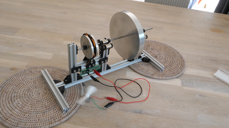
Of course, using a flywheel to store energy isn’t even close to being a new concept. But the principles [Tom] demonstrates in the video below, including the advantages of magnetically levitated bearings, are pretty cool to see all in one place. The flywheel itself is just a heavy aluminum disc on a shaft, with a pair of bearings on each side made of stacks of neodymium magnets. An additional low-friction thrust bearing at the end of the shaft keeps the systems suitably constrained, and allows the flywheel to spin for twelve minutes or more.
[Tom]’s next step was to harness some of the flywheel’s angular momentum to make electricity. He built a pair of rotors carrying more magnets, with a stator of custom-wound coils sandwiched between. A full-wave bridge rectifier and a capacitor complete the circuit and allow the flywheel to power a bunch of LEDs or even a small motor. The whole thing is nicely built and looks like a fun desk toy.
This is far from [Tom]’s first flywheel rodeo; his last foray into storing mechanical energy wasn’t terribly successful, but he has succeeded in making flywheels fly, one way or another.


Nice to see articles on magnetic bearings. Up till yesterday I haven’t found much that’s sophisticated enough to scale up to large size in ground installations without requiring a sizable power Freddie various corrections. I’m hypothesizing there’s room for a mix of magnetic circuits in geometric self orienting feedbacks mechanically sound & supporting tonnes of flywheels. Also haven’t yet seen a well done Net Present Costing usefully comparing with batteries.
Thanks for posting, worth a look, on my interest list especially for high current physics exploration ;-)
> Also haven’t yet seen a well done Net Present Costing usefully comparing with batteries.
And you won’t. Flywheels have too low power density for that.
Beacon Power has been using flywheels for grid-scale energy storage for many years.
True they don’t have the energy density of batteries, but they’ve got high power density, so are well suited for frequency stabilization applications.
Low density isn’t the only measure, yes a flywheel even really exotic, highly machined run in a vacuum flywheels will have its downsides to batteries, more than just lower density. But there are some upsides too – like the rate at which you can take energy out is generally much much higher than a battery, and most flywheels will be easy to maintain and cheap to build in comparison to batteries.
So there are very valid and useful comparisons to be made, in the same way you don’t put capacitors in place of batteries and visa-versa there are gains and losses that make it a good choice for some uses.
Not to mention that a flywheel has relatively low wear over time.
The ones used over at Beacon Power for an example use magnetic bearings, and run in a vacuum.
So not much wear going to happen there other than for the control logic and power circuits.
A battery bank on the other hand can rather easily wear out in 10-20 years time. Though, we have yet to see if the flywheels at Beacon Power will perform after such time, but they are proving themselves to be a somewhat useful solution, and they do beat batteries in short term energy storage, especially for the power. Self discharge is on the other hand abhorrent after just a couple of days…
I think batteries may best flywheels now, since you can pull 100-200C rates out of them. The challenge with flywheels is that loading them sets up mechanical vibrations which can throw the whole thing off balance and crash the magnetic levitated bearings.
>A battery bank on the other hand can rather easily wear out in 10-20 years time.
Batteries have a shelf-life. You don’t even have to use them.
The improvements in battery, and capacitors does mean a flywheel is more niche than it would have been not that long ago, but they are still not really direct competitors. 200C sounds impressive, but it is still peanuts to a flywheels potential…
So I’d never say batteries best flywheels flat out – but they might be best for this or that task.. And thanks to improvements over the last 40 odd years a battery or capacitor bank is now valid for more uses than it would have been.
The old Stronium Ferrite magnets that I once had tested at a University Lab in the 80’s came out like this. 2 groups of magnets both groups 1″ x 1″ x 3″. Group A brand new, and group B approx 15 years old. Group A tested at 1500-1600 gauss at zero distance. Group B varied between 1350 and 1400 gauss also at zero distance. So batteries may have a shelf life,(I think they are manufactured to fail to preserve the battery industry). But Strontium Ferrite magnets lose very little of their power over 15-20 years. Both groups of magnets were the same product no. and from the same source. I imagine that the new Neo-Dymium magnets from my supplier would have a similar shelf life. They are 3500-4000 gauss at zero distance I’ve been assured. Perpetual motion can definitely be achieved by having these magnets pre-set (strategically placed) during the casting of an aluminium flywheel. An aluminium housing surrounding the flywheel would also have magnets strategically placed during casting, to cause the flywheel to spin with huge torque. The idea being that the magnetic flywheel and corresponding housing becomes a perpetual motion machine to replace internal combustion engines and negate the need for fossil fuel. Would also negate the electric motor. This engine could easily drive a 230v generator that you see from hire companies that normally have a small petrol engine as motive force. To get more power? more flywheels and larger, with larger magnets and more of them.
Don… your comment started out so reasonable… why’d you have to end it with perpetual motion? Also for what it’s worth, I don’t believe batteries are manufactured to fail. They don’t need to be. Aside from the fact that they fail on their own, we consume such an incredibly vast quantity of electronic devices that even if batteries lasted forever, the demand for new batteries would still be sky-high.
Fool Bridzj Rectifiah!
https://www.youtube.com/watch?v=9dtPEk73X9U
The pointy end on one side of the axel gives a tiny bit of friction. Wouldn’t 2, strong enough, magnets with matching poles near one another on the axel and frame (on both ends of the axel) give even less friction?
Like:
Frame+NS SN+axel+SN NS+Frame
Yes, but it’s incredibly fiddly because the axle doesn’t want to sit straight. The ends will want to slip off to the sides, so the whole thing becomes quite wobbly.
now use a magnetic gearbox and a hand crank to spin it up!
Yay someone finally did a self balancing magnetic bearing without electronic feedback to keep the thing in position.
Something that I have heard plenty of physicists say is impossible. Since the magnets will always slide off, or flip around and attract each other.
But this is obviously not the case if one has an assembly keeping multiple magnets held in place. For one magnet to flip around, it needs to force another pair of repelling magnets closer to each other, and vice versa, it is simply a system relying on repelling forces only. And this case a bit of gravity to keep it in the cradle. (Repelling forces are practically negative feedback, attracting forces on the other hand is far far harder to keep balanced due to positive feedback.)
One could remove the thrust bearing at the end with another pair of magnets repelling each other, and then keep the whole thing in place by angling the whole device a little. Or adding another pair of magnets on the other side of the shaft as well.
Though, I guess air resistance is also holding this device back a little, putting in in an enclosure with reduced air pressure could likely keep it going for longer. (Doesn’t have to be an ultra high vacuum, just halving atmospheric pressure should make a noticeable difference.)
I were trying to do something similar a couple of years back myself, but had a less efficient solution that ended up having problems with the smoothness of the magnetic field. (Simply stated, making a fairly long circular track of individual magnets makes for a bumpy ride and nice losses.) The approach of using a small disk magnet and spinning that in a cradle is likely to have far less of such issues.
But I also do wonder about any eddy current losses in the aluminium disk. The extra distance between the bearings and the disk is likely helping to reduce any such losses.
Now the question is how much energy it stores and what losses it has.
Does it beat a capacitor bank is the question. (It likely beats capacitors in life expectancy if one puts the thing in a vacuum, since then corrosion and dust buildup isn’t an issue, and magnetic bearings don’t really wear out. So the bridge rectifier or driver might die first… Unlike caps that get progressively worse the longer they linger around.)
“But this is obviously not the case if one has an assembly keeping multiple magnets held in place. For one magnet to flip around, it needs to force another pair of repelling magnets closer to each other, and vice versa, it is simply a system relying on repelling forces only. And this case a bit of gravity to keep it in the cradle. (Repelling forces are practically negative feedback, attracting forces on the other hand is far far harder to keep balanced due to positive feedback.)”
Per Earnshaw’s theorem, you can’t actually do that. There are a few ways to cheat Earnshaw, such as using gyroscopic precession as a stabilizing force or diamagnetic materials, but they’re not all that useful for something like this. Spin stabilization only works in a relatively narrow band of rotation rates, and not at all at 0 RPM, so your bearings would crash as soon as the flywheel spun down enough. No known materials are strongly enough diamagnetic to work well in a practical bearing.
https://en.wikipedia.org/wiki/Earnshaw%27s_theorem
But it isn’t diamagnetism that we need to use. Just magnets repelling each other.
Two magnets alone can’t keep stability, and this I agree with.
But an assembly of magnets should logically be able to reach stability.
Lets take a very simple setup.
If you have two ring magnets that are axially magnetized (pair A). Where one is glued onto a table’s surface, and the other is held above it. Placed such that they do repel each other. Then this top ring would happily flip around.
But we can prevent that, by simply adding a counterweight. For this we will need to drill a hole in our table for a shaft to reach said counter weight. The counterweight prevents the levitating ring magnet from flipping around.
This system will however still slide parallel to the surface of the table.
But if we add another two ring magnets (Pair B), that are radially magnetized. Where we place one inside of the other in such a fashion that they too also repel each other. Our outer ring we glue to our table. The inner ring, we attach to our levitating axially magnetized ring from before. (Likely via some disk to keep the two magnet pairs sufficiently spaced apart to not interferer undesirably.)
This assembly won’t be able to move parallel to our table, since pair B will prevent that movement.
While the assembly can’t drop down to sit on the table’s surface, since pair A will prevent that.
Likewise the assembly can’t flip around, due to the counterweight. (That could likewise be the same assembly again but on the underside of the table. (as long as the two assemblies are sufficiently spaced apart for the radius of pair B to be well within the radius of our rotation during this flipping motion.))
This setup should work, statically just like dynamically.
Then we have Earnshaw’s theorem.
It doesn’t talk about two or more assemblies of point charges being held in place relative to each other. But rather multiple free charges able to roam about as they please. Assemblies binding the charges into well behaved groups isn’t considered nor talked about. Ie, Earnshaw’s theorem doesn’t apply in this context. So please stop misapplying it.
Earnshaw’s theorem places no requirements on how the point charges are arranged, or how they can move relative to each other.
“This theorem even applies to extended bodies that may even be flexible and conducting, as long as they are not diamagnetic. They will always be unstable to lateral rigid displacements of the body in some direction about any position of equilibrium. You cannot get around it using any combination of fixed magnets with fixed pendulums or suchlike.”
https://math.ucr.edu/home/baez/physics/General/Levitation/levitation.html
Want to prove Earnshaw wrong? Show me a stably levitating arrangement of ferromagnets with no other stabilizing forces.
Then I guess I will just have to buy a set of ring magnets of relatively custom diameters and polarization. And the only reason I haven’t done that so far in the last decade is because I don’t feel like spending that money, on something that is so trivial to prove on paper.
Just think about why it would and wouldn’t work, instead of taking some theorem as gospel.
Point out why and where it will fail, and why it can’t be fixed.
The described system above works with anything that achieves negative feedback with repelling forces. It can be springs, compressed air jets (the system described is actually a set of air bearings from a CNC spindel), or magnets.
Since magnetic fields falls into the inverse square law in how they effect things in their surroundings, then we can relatively easily ensure that the repelling forces are predominant above any attractive forces, and as long as we ensure that this remains the case, the system will be stable. This gives us an area of stability that we can consider the operating specs of our bearing system.
There are lots of extra forces in any stable levitation set up – as the whole point is to fight gravity, which can provide a useful external force that can tend the system to stability. You also have mechanical stresses in the parts involved – a setup that puts the axle under tension for instance can be held there because the magnets can’t overcome the axle or their mountings mechanical resistance. This isn’t really a situation where Earnshaw’s properly applies.
“Since magnetic fields falls into the inverse square law in how they effect things in their surroundings” is for single dipoles in space. Those force equations are for sources that can be considered to be points. In this magnetic bearing case, the magnets are close and much bigger than the size of the gap. Here there is no inverse r or r^2 and in the case of dipole to dipole near each other there is an inverse r^5 dependence. https://en.wikipedia.org/wiki/Force_between_magnets
I’m curious about this “negative feedback” and where it comes from?
Comedicles
True, the inverse square law doesn’t fully apply, but at least the distance for the attractive force is longer than that of the repelling one, ie, the repelling force is dominant. (though, flip the magnet over and it is the opposite.)
In regards to negative feedback.
It is practically any system that as it gets closer to the desired point, any input changes gets progressively smaller.
If we for an example have a track with a small cart on it with a magnet attached to said cart. And then two magnets on either end of the track that is placed such that the magnet on the cart will be repelled by our other two magnets.
If we in this example drag the cart fully over to one end of the track, then the cart will get forced down the track. As it progresses down the track, the repelling force gets smaller as the distance increases.
Though, as the cart gets closer to the other end, a new force will start to push it back to where it came.
If the movement of the cart is losseless, then it will now oscillate endlessly.
But in reality there is friction so it will eventually stop in the region where the two magnetic forces reaches equilibrium. (as long as the track is sufficiently short. On a long track then it will just stop somewhere inside of the region where the friction is dominant over any of the magnetic forces being applied.)
A system with positive feedback on the other hand is when the magnets on either end attracts the cart to them.
In this system, to get the cart to stay in the middle of the track, we then need to place it there perfectly. (Or within the region where friction is sufficiently dominant to counteract the combined magnetic forces.)
Calling it “feedback” is though likely incorrect of me. But I am drawing a parallel to operational amplifiers.
Alexander Wikström
I figured you were making an op-amp analogy. And I agree, it isn’t feedback. A feedback analogy would require that the feedback be able to change the magnetic field strength to control the position of the shaft. And you don’t have negative feedback you are into a whole different control theory, probably non-linear and intractable.
Aluminum is a terrible flywheel material. Low tensile strength. Very conductive, so eddy currents (even from Earth’s field) cause energy loss. Though can make a fine homopolar generator if you want to exploit that.
Very dinky flywheel. At Culham, there’s a pair of 776 tonne units that can in theory output 400 MW each. Their to part power the JET fusion project as it draws too steep a rate of change in power to take it all from the National Grid.
Obviously batteries would be the way to put it together now, but when designed in the 1970’s and built in the 80’s, giant flywheels were the way to go.
Giant flywheels is likely still the way to go.
Batteries aren’t that great at high power.
In short, taking a battery from fully charged to empty in less than 5 minutes is an impressive feat.
While for a flywheel, even large ones, then even a single minutes is a very long time.
Though, capacitors are even better if one wants tons of power but only needs it for a short duration. And capacitors are likely eating up the high peak power energy storage market faster than what batteries are doing. Especially considering how capacitor banks are even wandering into the UPS field… (Going from power outage to running backup generators only takes a few seconds, no reason for expensive batteries here.)
Giant flywheels have catastrophically low energy capacity per anything (same as those gravity batteries) + they have high price and maintenance cost and a potential to be very lethal.
They are only used in extremely specific special applications one of which Phil mentioned.
Care to tell how a large rotating block of something have higher maintenance costs than a capacitor bank or a battery pack? They are mostly “fire and forget”. Mechanical bearings wears out, sure, but magnetic coupling can do away with that. And apart from mechanical wear, what else would degrade? It’s not like the rotating mass would disappear with time.
Very lethal? Sure, but dig a hole and put them underground. Even a catastrophic disassembly would be easily contained and the damage would end in seconds and not threaten other flywheels on the same site if you space them enough. Now contain a fire on a MWh sized Li-Ion pack. It would burn for a very long time, and all packs around would be in danger.
Burning battery arrays is a fairly large issue. Fire suppression in battery rooms are fairly well thought out for a reason. (Though, depends on the battery room to be fair.)
Though, an exploding flywheel is likely also containing a lot of energy, though the thing with most mechanical structures is that they rarely just fail out of the blue. There is usually plenty of signs to say that something is wrong. A certain degree of safety factor is also common place making operations even more safe. So a flywheel failure is an unexpected event unless something else induces it.
Similar story for capacitor banks. They would under normal operating conditions not have many failure modes to worry about. If a cap goes shorted internally, then the film layers will self fuse. (this is true for lithium cells as well, and as part of product safety testing, ramming a nail through them is done. And it should fail in a controlled fashion. (and why all youtube videos of people ramming nails through batteries is almost always a bummer to watch.))
Worst thing for a capacitor bank is likely if someone drops a wrench between the terminals, or if a cable catches fire.
Though, for these high peak power applications, most of the equipment would be stone cold from the start. So there is plenty of thermal mass to absorb most of that energy, this means that heat induced fires is also unexpected.
But then when building something for peak power, pushing it to the edge isn’t an unexpected thing to be fair, so that something fails might not be abnormal, though, since one intentionally pushes everything to the edge, then a higher degree of safety surrounding the systems is likely taken into consideration.
“Care to tell how a large rotating block of something have higher maintenance costs than a capacitor bank or a battery pack?”
Sure. The lump might seem simple, but it’s all the rest of the kit that’s not and it’s a wee bit specialised.
At JET, the flywheels could hold about 1 MWh each at full chatt (give or take but never were wound up that fast so only ever held a fraction of the potential – making all metrics here much worse…). And they only returned ~47% (no idea how this was arrived at) of the energy put into them. The annual contract to run them, when all spares are taken into account was very much over £1M for the pair. Also required a team of 6 to 8 on shifts though they had other roles too, when not on main task.
For this you could buy 10 Teslas, abuse the batteries, throw them away, rinse and repeat, every year.
Obviously that wouldn’t deliver such high voltage and current as required by JET. But the point is, it’s not efficient or inexpensive. It’s also huge. Warehouse with evil villain style basement huge.
But it is very cool :)
Have costed smaller flywheel systems for smaller pulsed power projects and they’re always hideously expensive with preposterous maintenance contracts. But less so than the above.
I do think there’s a place for flywheels in energy infrastructure, but only where there’s already a rotating system that should maintain a constant rate. In essence, if all synchronous grid connected generators had a mandated minimum rotational kinetic energy to power ratio, frequency stability would be simplified (as long as the ratio was larger than it presently is in it’s no mandated form).
Phil
Outside of pulse power applications, flywheels aren’t that attractive as energy storage. Other than what Beacon Power over in New York is dealing with. Though, they achieve far higher efficiency than 47%, likely since they don’t care about peak power.
To what I have read, their system retains a round trip efficiency that is better than batteries for a 24-30 hour window. After that, losses starts adding up and it is on par with batteries for another few hours before eventually being beaten by them.
There is also synchronous condensers used for grid stabilization. These are in effect just large AC motors rotating a flywheel. These might become more common in the grid as more inverters are pushed onto the grid. It is a simple solution.
Using already existing AC motors is also an interesting idea. Though, can’t think of too many places myself were I have seen AC motors hooked up directly to the grid. Surprisingly many motors in industry has switched over to VFDs. (Since that allows for a smoother ramp up, less wear, the ability to pick any reasonable frequency aka RPM control, etc. etc…)
For pulsed power applications however.
I wouldn’t be surprised if flywheels starts getting more rare, capacitor banks are after all quite a good solution able to provide a lot of power with usually fewer items wearing out. Though, the ESR of capacitors tends to increase with time, leading to greatly larger losses, but the bank could be built sufficiently overkill for the losses down the road to be a rounding error overall. Ie, conductors from the bank to the application itself might be the bottle necks of the system.
And a MW worth of capacitors is honestly fairly cheap, though, if one wants a lot of energy too, then it becomes more expensive…
I like the phrase “outside of pulsed power they’re rare” :)
Aside from a UPS function in the Australian synchrotron, and the massive monsters at JET, I’m out of pulsed power installed flywheels. Rare here too :)
For the curious, the things I’d attempted to specify them for was part of a composite waveform for direct effcts lightning testing of aircraft. After a couple of straightforward capacative discharges on differing scales, a 1/2 second, 400 A arc is required across a 100 mm gap. Ideally driven by an inductivly stabalised and restively limited DC source of a few kV.
The flywheel would ideally have several times more energy than required and so not sag much over the discharge – though sagging was allowed.
Beacon was mentioned – they’re peak power was too low from their carbon fibre devices. We’d need at least 2 and it was going to cost about the same as 2 medium moons. So for about £150k, built a several MW 3ph buck converter with excessive capacitive energy storage and no ongoing (planned) maintance contracts. So no flywheels. A scheme to design one from scratch was cooked up but canned as too high a risk.
While there may be some merits in a whirling bit of material rather than a bucket of corosive goop. The corrosive goop market is so huge and cost effective now and the whirley storage still hediously expensive that it’s probably dead.
So just in case – let’s raise our morning coffee to the never to be fully realised at a large and country scale, useful level, world of grid connected flywheel energy storage.
The money’s wrong as the decimal point is in the wrong place.
Could be wrong, and if so, one day shall raise an afternoon cup of coffee in celebration of its success ;)
I don’t really know what you are trying to get at here.
I did only talk about power delivery and that batteries aren’t that useful as far as reaching higher power discharges for short durations. Ie, the Watts per dollar is better for flywheels and capacitors than what it is for batteries. The Watt hours per dollar on the other hand is the complete opposite, but that is besides the point.
That it is only a few niche applications using flywheels in this fashion is true. And capacitors are having certain advantages that has seen them venture into related markets with similar focus on short term power delivery.
Uses aluminum instead of steel so it doesn’t Interfere with magnetic field of bearings… Glues even bigger magnets to the other wheel.
Hard Disk Drives don’t quite have a frictionless bearing. But their ferrofluid bearing does have a long lifetime, and their structure is already pretty well set up for a flywheel based energy storage system. It really wouldn’t be efficient, but you could grab a ton of scrap hdds, fit them with custom motor drivers, and build a big ol’ battery out of them ;)
Haha I found a terrible patent with a similar idea:
https://patents.google.com/patent/US5714812
Also nobody do this I might make a video out of this (>,<)