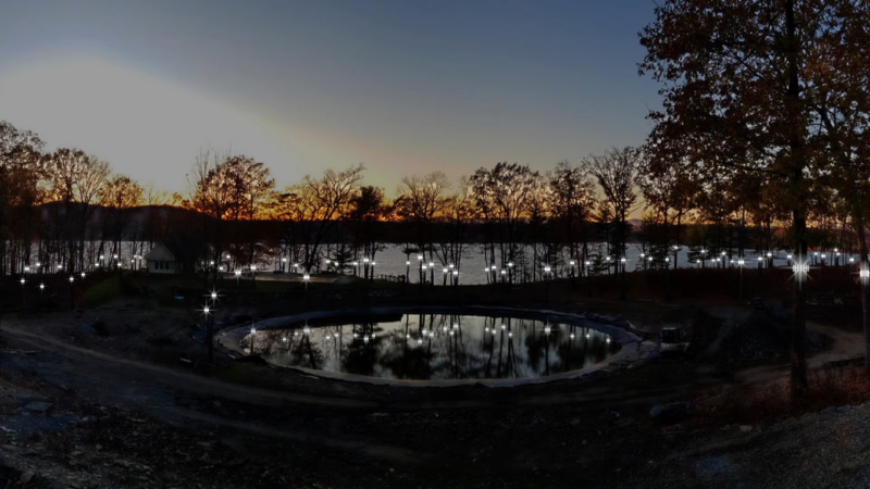
Normally, when a project calls for addressable LEDs, we just throw a strip of WS2812s and an Arduino together, cobble together some code from the examples in the FastLED library, and call it a day. We don’t put much thought into what’s going on under the hood, unless and until we run into an LED project that’s a little more challenging.
Inventor [Leo Fernekes] found himself in such a situation recently, when he pitched in on an LED art installation. The project called for rings of LED bars around the trunks of trees on a private estate. The physical size of the project and the aesthetic requirements created significant challenges, though. One of these was finding a way to control the LED bars, each of which draws about 100 mA and needs to be very smoothly dimmed. [Leo] looked at the WS2811 LED driver, but found that the low drive current and the 8-bit PWM output failed to tick either of those boxes.
[Leo] solved both problems by using two of the three PWM channels on the chip in concert — one to control the current and one to PWM the LED. The circuit he came up with is deceptively simple — just four transistors, a Schottky diode, and a bunch of passives. The other clever bit is the data interface between LED bars, which can be configured as either single-ended or differential. This allows the same interface to be used for the short distance between bars on a tree, and the longer runs between trees.
As usual, [Leo] does a great job of explaining his design and how it works, which we find very instructional. He did something similar when he managed to dim a non-dimmable LED fixture.


Firefly effect would be more pleasing.
Man, rich people spend money on weird crap.
Well when they don’t pay taxes, they have to find creative ways to use up all that money!
@ 6:40
95% + 10% = …….100%??! 🤣🤣🤣
Hm, the claim that the ws2811 has a builtin gamma correction is news to me. Isn’t the whole problem with the coarse resolution in low intensities due to *no* gamma correction?
There is an inherent weakness in numerical control at small values. No matter what, the difference between 1 and 2 is a bigger jump than between 30 and 31. This cannot be overcome with a correction table of any kind. What they did here was essentially add more bits to raise the floor on the resolution.
Erm… it’s fixable with a log conversion on the output.
Do you mean in an analog way after the PWM? I’d like to know more about how that would work.
+1
?? How ?? The least significant bit ‘on’ represents the shortest possible PWM interval, the next bit up doubles the value, a 100% change in brightness. No way around that.
In an ideal world you’d use more bits on the output than on the input. For the non-ideal ws2812 LEDs I typically use a gamma table where in the low end a lot of values are duplicated, grudgingly accepting the not-dark-enough “1” value.
There also are mechanisms like e.g. implemented in the “FadeCandy” which uses “temporal dithering” by sending the LEDs alternating values, but this needs short LED strips for a high update frequency.
What I was wondering is, could we use the 3 outputs to drive a passive R-2R resistor ladder DAC. So the LSD on one channel would be worth half as much as the LSB on the next channel, and so on. Then again with passives we’re wasting power, so probably not a great solution. Anyway was just something I was thinking of when watching your video. With the built in gamma correction it probably would not have been a good solution. Anyway food for thought
They do have a small bit of correction in them; it’s helpful but isn’t a total solution. Here are graphs of the output brightness and current vs PWM setting for the similar WS2813 IC, that shows the correction at the low end:
https://twitter.com/cibomahto/status/1385358870831316994
This looks a lot like what I usually do and how I work :-)
https://hackaday.io/project/16943-pixelavenue
https://hackaday.io/project/8308-ws2811-power-dac
https://hackaday.io/project/6955-rosace
https://hackaday.io/project/6954-mons2015-led-screen-electrosuper
and more that I haven’t covered on HaD.io …
For one project that is installed at the Roissy airport, I implemented 14-bit PDM with FPGA to satisfy the artist’s demanding requirements…
Anyway, the current+pulse trick described there is awesome :-)
Now, what do we do with the remaining channel ?
That’s what I was thinking. He picked up 8 bits, but left 8 more still on the floor! :)
Leo seems like an all around awesome person and I’m happy for him that he gets to work on interesting projects like this one.
That’s awesome. It’s not clear how he planned for tree diameter expansion though. I hope he did…
I envy your skills. Very nice to see how you succesfully manage to control the WS2811 on a long distance. Great use of LED COBs. Would be great to see if it would also be managable via DMX512.
https://www.brucemunro.co.uk/ might be using something similar…???