1950s Fighter Jet Air Computer Shows What Analog Could Do

Imagine you’re a young engineer whose boss drops by one morning with a sheaf of complicated fluid dynamics equations. “We need you to design a system to solve these equations for the latest fighter jet,” bossman intones, and although you groan as you recall the hell of your fluid dynamics courses, you realize that it should be easy enough to whip up a program to do the job. But then you remember that it’s like 1950, and that digital computers — at least ones that can fit in an airplane — haven’t been invented yet, and that you’re going to have to do this the hard way.

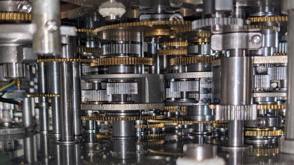
The scenario is obviously contrived, but this peek inside the Bendix MG-1 Central Air Data Computer reveals the engineer’s nightmare fuel that was needed to accomplish some pretty complex computations in a severely resource-constrained environment. As [Ken Shirriff] explains, this particular device was used aboard USAF fighter aircraft in the mid-50s, when the complexities of supersonic flight were beginning to outpace the instrumentation needed to safely fly in that regime. Thanks to the way air behaves near the speed of sound, a simple pitot tube system for measuring airspeed was no longer enough; analog computers like the MG-1 were designed to deal with these changes and integrate them into a host of other measurements critical to the pilot.

To be fair, [Ken] doesn’t do a teardown here, at least in the traditional sense. We completely understand that — this machine is literally stuffed full of a mind-boggling number of gears, cams, levers, differentials, shafts, and pneumatics. Taking it apart with the intention of getting it back together again would be a nightmare. But we do get some really beautiful shots of the innards, which reveal a lot about how it worked. Of particular interest are the torque-amplifying servo mechanism used in the pressure transducers, and the warped-plate cams used to finely adjust some of the functions the machine computes.

If it all sounds a bit hard to understand, you’re right — it’s a complex device. But [Ken] does his usual great job of breaking it down into digestible pieces. And luckily, partner-in-crime [CuriousMarc] has a companion video if you need some visual help. You might also want to read up on synchros, since this device uses a ton of them too.

Continue reading “1950s Fighter Jet Air Computer Shows What Analog Could Do”

Inside Globus, A Soviet-Era Analog Space Computer

Whenever [Ken Shirriff] posts something, it ends up being a fascinating read. Usually it’s a piece of computer history, decapped and laid bare under his microscope where it undergoes reverse engineering and analysis to a degree that should be hard to follow, but he still somehow manages to make it understandable. And the same goes for this incredible Soviet analog flight computer, even though there’s barely any silicon inside.

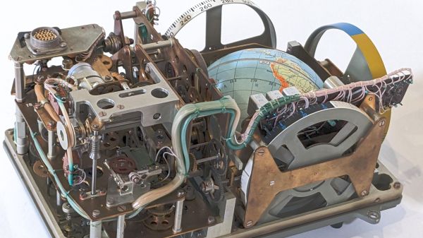
The artifact in question was officially designated the “Индикатор Навигационный Космический,” which roughly translates to “space navigation indicator.” It mercifully earned the nickname “Globus” at some point, understandable given the prominent mechanized globe the device features. Globus wasn’t actually linked to any kind of inertial navigation inputs, but rather was intended to provide cosmonauts with a visual indication of where their spacecraft was relative to the surface of the Earth. As such it depended on inputs from the cosmonauts, like an initial position and orbital altitude. From there, a complicated and absolutely gorgeous gear train featuring multiple differential gears advanced the globe, showing where the spacecraft currently was.

Those of you hoping for a complete teardown will be disappointed; the device, which bears evidence of coming from the time of the Apollo-Soyuz collaboration in 1975, is far too precious to be taken to bits, and certainly looks like it would put up a fight trying to get it back together. But [Ken] still manages to go into great depth, and reveals many of its secrets. Cool features include the geopolitically fixed orbital inclination; the ability to predict a landing point from a deorbit burn, also tinged with Cold War considerations; and the instrument’s limitations, like only supporting circular orbits, which prompted cosmonauts to call for its removal. But versions of Globus nonetheless appeared in pretty much everything the Soviets flew from 1961 to 2002. Talk about staying power!

Sure, the “glass cockpit” of modern space vehicles is more serviceable, but just for aesthetics alone, we think every crewed spacecraft should sport something like Globus. [Ken] did a great job reverse-engineering this, and we really appreciate the tour. And from the sound of it, [Curious Marc] had a hand in the effort, so maybe we’ll get a video too. Fingers crossed.

Thanks to [saintaardvark] for the tip.

Building A Chain Drive Differential From Junkyard Parts

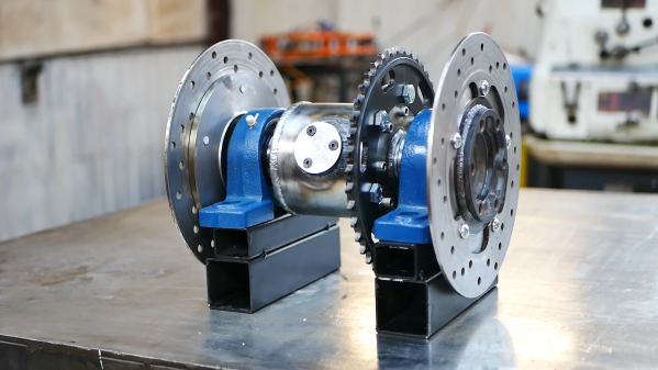
A differential is a very useful thing for a vehicle. It allows two driven wheels to rotate at different speeds, such as when going around a corner. [Workshop From Scratch] needed a chain driven differential, so set about building one from a salvaged automotive unit.

The differential itself was taken from a BMW E46 3-Series, specifically a 2.0-liter diesel model. The work began by removing the differential’s center gears from its big, hefty iron housing. Disassembly then ensued, with the spider gears removed from their carrier and the other components discarded. The differential gears themselves were installed instead in a new compact housing, fabricated with much welding and lathery. The housing was fitted with a large chain sprocket to deliver drive, in place of the original differential’s ring gear and pinion.

The video’s description states it would be an ideal differential for a go-kart, buggy, or other such small vehicle. Given the differential gears were originally built to handle a full-sized car, they should be more than capable of dealing with such applications.

If you’re a little unfamiliar with how differentials work, check out this primer from the early 20th century. It’s widely considered to be the best education on the topic. Video after the break.

Continue reading “Building A Chain Drive Differential From Junkyard Parts”

Cool WS2811 Trick Makes LED Art Installation Smooth

Normally, when a project calls for addressable LEDs, we just throw a strip of WS2812s and an Arduino together, cobble together some code from the examples in the FastLED library, and call it a day. We don’t put much thought into what’s going on under the hood, unless and until we run into an LED project that’s a little more challenging.

Inventor [Leo Fernekes] found himself in such a situation recently, when he pitched in on an LED art installation. The project called for rings of LED bars around the trunks of trees on a private estate. The physical size of the project and the aesthetic requirements created significant challenges, though. One of these was finding a way to control the LED bars, each of which draws about 100 mA and needs to be very smoothly dimmed. [Leo] looked at the WS2811 LED driver, but found that the low drive current and the 8-bit PWM output failed to tick either of those boxes.

[Leo] solved both problems by using two of the three PWM channels on the chip in concert — one to control the current and one to PWM the LED. The circuit he came up with is deceptively simple — just four transistors, a Schottky diode, and a bunch of passives. The other clever bit is the data interface between LED bars, which can be configured as either single-ended or differential. This allows the same interface to be used for the short distance between bars on a tree, and the longer runs between trees.

As usual, [Leo] does a great job of explaining his design and how it works, which we find very instructional. He did something similar when he managed to dim a non-dimmable LED fixture.

Continue reading “Cool WS2811 Trick Makes LED Art Installation Smooth”

The Case Of The Mysterious Driveline Noise

Spend enough time on the automotive classifieds and you’ll end up finding a deal that’s too good to pass up. The latest of these in one’s own case was a Mercedes-Benz sedan, just past its twentieth birthday and in surprisingly tidy condition. At less than $3,000, the 1998 E240 was too good to pass up and simply had to be seen.

The car in question. Clean bodywork is too tempting to resist, even if there are mechanical issues.

The car was clean, too clean for asking price. Of course, a test drive revealed the car had one major flaw – an annoying hum from the drivetrain that seemed to vary with speed. Overall though, mechanical problems are often cheaper and easier to fix than bodywork, so a gamble was taken on the German sedan. The first order of business was to diagnose and rectify the issue.

Characterise, Research, Investigate

The first step to hunting down any noise is to characterise it as much as possible. In this case, the noise was most noticeable when the car was traveling at speeds from 40 km/h – 60 km/h, present as a vibrational humming noise. The location of the noise source was unclear. Importantly, the noise varied with the speed of the car, raising in pitch at higher speeds and dropping as speeds decreased. Engine speed had no effect on noise whatsoever, and the noise was present regardless of gear selected in the transmission, including neutral. Continue reading “The Case Of The Mysterious Driveline Noise”

Differential Drive Doesn’t Quite Work As Expected

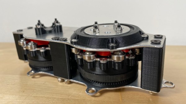
Placing two motors together in a shared drive is a simple enough task. By using something like a chain or a belt to couple them, or even placing them on the same shaft, the torque can be effectively doubled without too much hassle. But finding a way to keep the torque the same while adding the speeds of the motors, rather than the torques, is a little bit more complicated. [Levi Janssen] takes us through his prototype gearbox that attempts to do just that, although not everything works exactly as he predicts.

The prototype is based on the same principles as a differential, but reverses the direction of power flow. In something like a car, a single input from a driveshaft is sent to two output shafts that can vary in speed. In this differential drive, two input shafts at varying speeds drive a single output shaft that has a speed that is the sum of the two input speeds. Not only would this allow for higher output speeds than either of the two motors but in theory it could allow for arbitrarily fine speed control by spinning the two motors in opposite directions.

The first design uses two BLDC motors coupled to their own cycloidal drives. Each motor is placed in a housing which can rotate, and the housings are coupled to each other with a belt. This allows the secondary motor to spin the housing of the primary motor without impacting the actual speed that the primary motor is spinning. It’s all a lot to take in, but watching the video once (or twice) definitely helps to wrap one’s mind around it.

The tests of the drive didn’t go quite as planned when [Levi] got around to measuring the stall torque. It turns out that torque can’t be summed in the way he was expecting, although the drive is still able to increase the speed higher than either of the two motors. It still has some limited uses though as he notes in the video, but didn’t meet all of his expectations. It’s still an interesting build and great proof-of-concept otherwise though, and if you’re not clear on some of the design choices he made there are some other builds out there that take deep dives into cycloidal gearing or even a teardown of a standard automotive differential.

Continue reading “Differential Drive Doesn’t Quite Work As Expected”

All-Wheel Drive Bicycle Using Hand Drill Parts

A skilled mountain biker can cross some extreme terrain, but [The Q] thought there might be room for improvement, so he converted a fat bike to all-wheel drive.

The major challenge here is transferring pedal power to the front wheels, especially around the headset. [The Q] solved this by effectively building a differential from the parts of a very old hand drill. Since the front wheel needs to rotate at the same speed as the rear, one long chain loops from the rear wheel to the headset, tensioned by a pair of derailleurs. This front sprocket turns a series of spur gears and bevel gear arranged around the headset, which transfers the power down to the front wheel via another chain.

It would be interesting to feel what the bike rides like in soft sand, mud, and over rocks. We can see it has some advantages in those conditions but were unsure if it would be enough to offset the penalty in weight and complexity. The additional chains and gears certainly look like they’re asking to catch foliage, clothing, and maybe even skin. However, we suspect [The Q] was more likely doing it for the challenge of the build, which we can certainly appreciate. With the rise of e-bikes, adding a hub motor to the front wheel seems like a simpler option.

We’ve seen several interesting bicycle hacks over the years, including a strandbeest rear end, 3D printed tires and an automatic shifter. Continue reading “All-Wheel Drive Bicycle Using Hand Drill Parts”