
You’ve probably encountered this before — you have a circuit board that is poorly documented, and want to know the part number of a tiny SMD chip. Retro computer enthusiast [JohnK] recently tweeted about one such database that he recently found, entitled The Ultimate SMD Marking Codes Database. This data base is only a couple of years old judging from the Wayback Machine, but seems to be fairly exhaustive and can be found referenced in quite a few electronics forums.
Unlike their larger SMD siblings, these chips in question are so small that there is no room to print the entire part number on the device. Instead, the standard practice is for manufacturers use an abbreviated code of just a few characters. These codes are only unique to each part or package, and aren’t necessarily unique across an entire product line. And just because it is standard practice does not imply the marking codes themselves follow any standard whatsoever. This seemingly hodgepodge system works just fine for the development, procurement and manufacturing phases of a product’s lifecycle. It’s during the repair, refurbishment, or just hacking for fun phases where these codes can leave you scratching your head.
Several sites like the one [JohnK] found have been around for years, and adding yet another database to your toolbox is a good thing. But none of them will ever be exhaustive. There’s a good reason for that — maintaining such a database would be a herculean task. Just finding the part marking information for a known chip can be difficult. Some manufacturers put it clearly in the data sheet, and some refer you to other documentation which may or may not be readily available. And some manufacturers ask you to contact them for this information — presumably because it is dynamic changes from time to time.
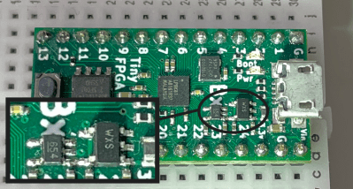
As a quick example of the pitfalls encountered when using these reverse lookups databases, consider two small-footprint SMD parts from a Tiny FPGA module that is sitting on my desk. Using the database that [JohnK] posted, the WXS is most likely a 3.2 V LDO by Richtek, part number RT9013-31GB. But WXS is also the code for a 3-pin PNP transistor. Richtek themselves says the RT9013 should be marked WX=, but that is based on a document from 2009. Richtek is one of the companies that says to contact them for the latest marking codes, so this may have changed in the past ten years.
The other chip marked 654 is more than likely a linear voltage regulator, such as the Micrel MIC5365-1.2YCV5. Here is a situation, presumably by coincidence, where several manufacturers are using the same code to represent different kinds of chips — interestingly all of them power supply circuits. Except for the Micrel part, the others all generate 5.4 VDC. For an FPGA board that probably uses 1.2 V, it’s reasonable to rule out those others. As you can see, knowing the package details and guessing the basic function of the chip can help narrow things down. Even though these lookups aren’t perfect, finding a match in the database and considering other things you know about the chip means you can usually find the information you want.
In the future, will we have a web-crawling AI who automatically generates and maintains such a database, even calling the manufacturers to obtains codes that aren’t published online? What is your favorite go-to site for looking up these codes? Let us know in the comments below. Thanks to [J. Peterson] for sending bringing this to our attention via the tips line.


And how do you know it is WXS not SXM?
A common practice is to make the top loop of the ‘S’ is a little smaller than the bottom loop. Further, the sides of a W are usuallly mutually slanted while the sides of an M are parallel. To my eye, these help orient the characters.
Reading from the right side most? Most companies it reads from pin 1 or in some cases to pin 1.
Sometimes it helps to search for a picture on Google.
It might not solve all problems, but it’s far better than not having this search option.
If you don’t know the orientation of the component, you can’t always tell, but in this case it’s a pretty safe bet. Most of these marking fonts have distinctions between easily-confused letters and numbers. If it has slanted sides it’s almost certainly a W – straight sides for an M. There are, of course exceptions – some extra tiny fonts will have straight-sided Ws, and the Motorola logo is a very common example of a slant-sided M.
Sometimes I wonder why component makers don’t just make the text even smaller and add a few more characters.
Though, considering how some component makers add really poor almost unreadable text to begin with, then maybe this isn’t a good solution. After all, some counterfeit chips are obvious due to having perfectly clear text on them.
I guess the target group for the text is the assembly and test people, not the repair or hack or recycle people. I hope the “circular economy” idea reaches them at some point.
It’s hard and very expensive to make the marking smaller.
Not the easiest front page to look at but very useful. Nice!
I am not sure if best way to enter two letters is to offer all possible combinations :-) It might make sense when searching using touchscreen, but text input using keyboard would be a viable option as well if available.
Anyway. I was looking for such database for a long time, so i am happy, that someone actually did it. yay!
BTW does it decode SMD resistor values as well?
SMD resistor values are very often just following the XXY pattern, where X is the two first digits, and Y is the number of zeros following.
Ie, 100 ohm is 101
10 ohm is 100
And 10M ohm is 106
Though, some manufacturers also use letters and get more intricate…
Resistors also rarely are bellow 1 ohm unless it is a shunt, and then it isn’t too common to have an R or an E in front of the number. Like E01 for 0.01 ohm.
I’m sure this will come in handy one day, bookmarked!
Agree
This is exactly what I needed!
If you need to decode resistor chip values, there is this page: http://kiloohm.info/smd3-resistor/100
Where is the AI to do the work?
I’m positive that SOT23 part is Micrel/Microchip MIC5504-3.3YM5, a 3.3V LDO. Source: I use them by the boatload. Also confirmed in the datasheet.
Referring to the part with the WXS marking
Which other sites are you using?
My bookmarks have http://info.electronicwerkstatt.de/bereiche/bauteile/ic_logo and chip.tomsk.ru/chip/chipdoc.nsf/ although the latter seems to be down and I hope not gone…
https://web.archive.org/web/20210614161112/chip.tomsk.ru/chip/chipdoc.nsf/
looks very useful too
I like https://www.s-manuals.com/
A great addition to this would be to have (right next to the ID) a small picture of the package (as the package is listed anyway) so the looker-upper doesn’t have to work out what a DO-214AA or whatever looks like.
You could have it as an option for those who retain this info in their heads and would find it annoying.
Wow, this is huge. Bookmark’d.
I personally use (or used) https://www.s-manuals.com/ru/smd While it’s not not as large it has datasheets (for each part) and package depictions (for the most parts) included. The downside is the part descriptions are mostly in Russian.
What has always bothered me:
SMD resistors have their values marked with 3 or 4 digits. OK.
But SMD capacitors don’t have any numbers written on them.
WHY???
If the objects are this small to not fit a full description, they are already not human friendly just because of their size.
How am I supposed to solder the tiny pads reliably with my normal sized hands?
You know the TSSOP package?
The first two letters of this acronym stand for “Terribly Small”.
> TSSOP … acronym
If not pronounced as a word, it’s an *initialism*.
Cool! Despite being Absolutely useful (thanks for the articke), we can reverse its usage and buy some components to form our names or at least some mneumonic.
It would be neat to has an offline version of this !
Why worry about not being able to decode them. I can’t even SEE them! For the last few years before I gave up, was buying microscopes, optical and electronic, but that’s a whole ‘nother layer of work and expense on top of just doing the hobby like was used to. Still did a LOT of development, but the fun just wasn’t there anymore. Whomever though, inherits my parts stock… they’ll be SET!
What does R01 and R001 on a SMD mean?
Most likely resistors with the following values.
R01 = 0.01 ohm
R001 = 0.001 ohm