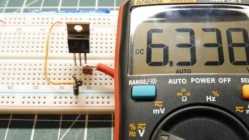
It’s late at night. The solder smoke keeps getting in your tired eyes, but your project is nearly done. The main circuit is powered by your 13.8 V bench supply, but part of the circuit needs 9 V. You dig into your stash to find your last LM7809 voltage regulator, but all you have is a bunch of LM7805’s. Are you done for the night? Not if you’ve watched [0033mer]’s Simple Electronic Circuit Hacks video! You know just what to do. The ground pin of a LM7805 connects to the cathode of a TL431 programmable Zener diode pulled from an old scrapped TV. The diode is referenced to a voltage divider, and voila! Your LM7805 is now putting out a steady 9 V.
How did [0033mer] become adept at doing more with less? As he explains in the video below, his primary source of parts in The Time Before The Internet was old TV’s that were beyond repair. Using N-Channel MOSFETs to switch AC, sensing temperature changes with signal diodes, and even replacing a 555 with a blinking LED are just a few of the hacks covered in the video below the break.
We especially appreciated the simple, to-the-point presentation that inspires us to keep on hacking in the truest sense: Doing more with less! If you enjoy a good diode hack like we do, you will likely appreciate learning Diode Basics by W2AEW, or a Diode Based Radiation Detector.
Thank you [DSM] for the tip! Be sure to submit your the cool things you come across to our Tips Line!


There’s a old “trick” almost as old as the original LM309 5V regulator, to convert any 3 terminal into an adjustable regulator whose output voltage is GREATER than the regulator’s. This was developed before “adjustable” 3 terminal regulators like the LM317. Just use the “basic” LM317 circuit to do it (like this one: https://www.electronics-tutorial.net/wp-content/uploads/2015/09/VR7.png). This only requires two resistors (both fixed if you have the right ones, or one fixed and one adjustable if you don’t). The tradeoff is that this technique sacrifices some output regulation due to variation in operating current through the bootstrap resistor. It works OK because of the ground terminal current is low due to the regulator’s high gain. Using the TL431 eliminates that regulation loss, but even with the TL431, the regulation of the combined circuit is the some of the 3 terminal regulator PLUS that of the TL431.
I’m not looking, but I suspect this sort of trick is in the datasheet or application note for the 309.
And yes, it was the 309 that I first read about, “on card regulator”, so much simpler than previous voltage regulators.
I recently picked up a powered breadboard from a thrift shop — one of those classic jobs from Global with a sheet metal chassis and a three-voltage power supply, just banana jack binding posts for ground, +5v, +15v, and -15v. (Still available new from Digikey for around $250!)
Anyway, I opened it up to see if I could adjust it to do ±12v instead of ±15v, expecting either that I’d have to swap in 7812 and 7912 for its 7815 and 7915, or that it’d have trimmers for an LM317/LM337 pair. I found two trimmers, all right, and they turned the voltage to what I wanted, but it really surprised me that all three 3-terminal voltage regulators were 7805s.
Lifting the ground reference up from the ground to increase output voltage is right in the LM78xx datasheet application notes, and it doesn’t need programmable zeners – just two resistors.
The TL431 is also not a “programmable zener diode” but an adjustable shunt voltage regulator, so the hack is to adjust the output voltage of a regulator… using a voltage regulator. If you have a TL431 you don’t need the LM7805, you can use some random NPN transistor as the pass element. The circuit is in the datasheet application notes, and on the wikipedia page…
Thinking quickly, dave fashions a homemade voltage regulator, using only a voltage regulator, two resistors, and a voltage regulator.
You don’t even need a regulator. You can just chain diodes. Not pretty but functional. If it is a consistent load you can use a resistor. How hacky do you want to get?
And diodes, and I think zeners, were a solution before the two resistors, at least that’s what I remember.
Isn’t a chain of diodes exactly what’s shown in the top image of the post?
I love it !
But blinking LED are extinct species.
So Hail to 555 !
Maybe a twinkle Christmas light might be an ok replacement? Not as efficient but maybe more readily available.
I thought I saw blinking LEDs at amazon.
The explanation for the last circuit is incorrect; he says only one of the MOSFETs is on in each half-cycle, and the current flows through the body diode of the other. This is not true; both MOSFETs have a positive gate-source voltage, so both are conducting, and a conductive MOSFET can actually conduct current in either direction equally well (where a BJT or IGBT cannot).
The reason you need 2 MOSFETs in anti-series is that each can only block the current in one direction, because of the body diode; both must be off to prevent current flow in both half-cycles.
This circuit can be useful, but I feel he is cheating by using a 9V battery to drive the MOSFETs; you either need a floating supply, but that is usually very inconvenient in a larger circuit, or a much more complicated driver arrangement. Also, it should be noted this circuit is unsuitable to switching inductive loads, as there is no path for the current after switching off, which would normally be provided by the flyback diode in a DC circuit, and there is no trivial way to provide such a path.
Great tips! Forest Mims, where are you?
This helps me rationalize keeping the pounds of salvaged parts I’ve acquired from dismantling thrown-out electronics. My wife hates HaD…
Wait, you throw out electronics?
I personally find old, functional, but no longer desired electronics are a trove of useful parts as well as circuit insights.
Forrest Mims is still writing occasional articles for MAKE, usually on citizen scientist topics — I think the other science magazines dumped him a couple of decades ago when he was making a lot of noise about being a creationist.
I think Science Probe! magazine just wasn’t successful. Published by Gernsback, I think Mims was editor, and it was sort of about science fair projects.
It was Scientific American that dropped him from his role writing The Amateur Scientist column because of his religious beliefs.
I needed 6 Volts but only had 7805s on hand. But also, 1N4004 diodes. Two diodes in series with the “Ground” terminal to curcuit ground got me close enough for my circuit to work.
He said he salvaged parts from thrown-out electronics – he didn’t say that he was the one throwing out the electronics that he was salvaging parts from. I’ve savaged lots of parts from stuff thrown out by other people, and have been doing so for more than 50 years.
Let me guess – you spend a lot of time on Facebook or similar social media. Lately I’ve noticed an alarmingly large number of posts on various forums where people very clearly didn’t fully read the (usually short) posts they were responding to – they simply reacted to some key phrase or sentence. My best guess is that the prevalence of short attention spans is a result of the way in which most people now consume media. Sound bites are not stories folks!