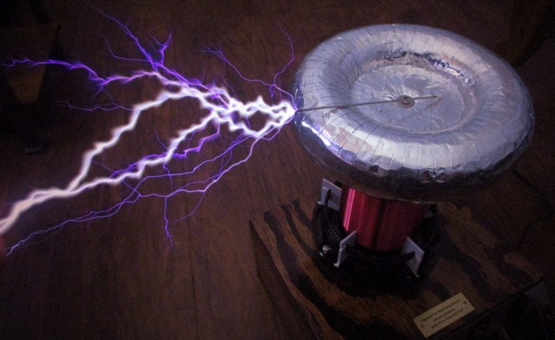
[Zach Armstrong] presents for your viewing pleasure a simple guide to building a solid-state Tesla coil. The design is based around a self-resonant setup using the UCC2742x gate driver IC, which is used in a transformer-coupled full-wave configuration for delivering maximum power from the line input. The self-resonant bit is implemented by using a small antenna nearby the coil to pick up the EM field, and by suitably clamping and squaring it up, it is fed back into the gate driver to close the feedback loop. Such a setup within reason allows the circuit to oscillate with a wide range of Tesla coil designs, and track any small changes, minimizing the need for fiddly manual tuning that is the usual path you follow building these things.
Since the primary is driven with IGBTs, bigger is better. If the coil is too small, the resonant frequency would surpass the recommended 400 kHz, which could damage the IGBTs since they can’t switch much faster with the relatively large currents needed. An important part of designing Tesla coil driver circuits is matching the primary coil to the driver. You could do worse than checkout JavaTC to help with the calculations, as this is an area of the design where mistakes often result in destructive failure. The secondary coil design is simpler, where a little experimentation is needed to get the appropriate degree of coil coupling. Too much coupling is unhelpful, as you’ll just get breakdown between the two sides. Too little coupling and efficiency is compromised. This is why you often see a Tesla coil with a sizeable gap between the primary and secondary coils. There is a science to this magic!
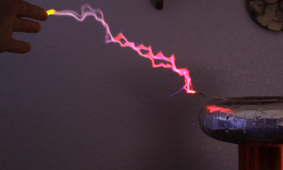
A 555 timer wired to produce adjustable pulses feeds into the driver enable to allow easily changing the discharge properties. This enables it to produce discharges that look a bit like a Van De Graaff discharge at one extreme, and produce some lovely plasma ‘fire’ at the other.
We’ve covered Tesla coils from many angles over the years, recently this plasma tweeter made sweet sounds, and somehow we missed an insanely dangerous Tesla build by [StyroPyro] just checkout that rotary spark gap – from a distance.


Happy Halloween!! I built my first TC as a kid in the late 60s with glass plate capacitors and a couple of neon sign transformers and have helped build a dozen or so since. Time to build another one!
The same here except I had a oil furnace ignition transformer with the secondary grounded in the middle, that meant I couldn’t ground one end, the teacher pointed this out. So I made the only balanced terminal ended horizontal coil I have ever seen. My dad brought home solid wood crates from Alcoa and I enclosed all but the Tesla coils inside with the spark gap visible in a glass window in the front and the glass cap in the back.
I pointed out to the judges at the science fair that my setup was safer than the other half dozen in the gym for enclosing the worst of the high voltage where all as the others were on large breadboards, as well as the half as much voltage on the primary to ground. Of course no one thought of those things then in a school full of kids. 3rd place!
“(…) UCC2742x gate driver IC, which is used in a transformer-coupled full-wave configuration for delivering maximum power from the line input.” – this is simply not true. First of all, the configuration name you meant is called “full-bridge”, not “full-wave”. Second, this circuit is a half-bridge configuration. For full-bridge one needs four switching transistors. The power delivered is limited by the tank capacitors. That’s also the reason why transistors blow when the equivalent impedance of the primary coil is less than 6Ω…
The GDT failure caused by the use of magnet wire was actually caused by the lack of knowledge. [Zach Armstrong] probably used low-voltage magnet wire which he slapped directly on the core. It also probably wasn’t selected for the currents it would have to handle. Such gaps in knowledge are typical for most TC builders – they are kludging together some high-voltage switching converters with little to no knowledge about any switching converters. His PCB design is ugly, too…
I also saw similar self-oscillating TC circuits before. 15-20 years ago, to be exact…
“full wave” probably refers to the use of a full bridge rectifier in the mains input path.
Transistors (and other components) blow because people try to run these things near the margins, so they get the biggest sparks. It has nothing to do with “low voltage” magnet wire, or not “selecting for currents”.
You want the transistors to switch at high speed, with high voltage and high current, and you want them for a reasonable price. That doesn’t exactly leave much choice.
Well, I’d hate to break it to you…but the magnet wire failure was not from lack of knowledge. The magnet wire was high-voltage rated and thick enough to handle the currents, the windings simply sparked and shorted when they touched each other. This having happened, I recommended that people use proper insulated wire, since it doesn’t really have this issue.
And thank you for your thoughts on my PCB quality. It was my first attempt at a proper PCB, so there’s no surprise why it didn’t turn out like one designed by a master engineer with years of experience. Hopefully the PCB for my latest staccato QCW DRSSTC is slightly more to your liking!
Haha, YES that Staccato QCWDRSSTC is a beautiful beast! Great work on it, & the vid.
Typical magnet wire is rated in static tests at 4kV, but in practice it’s usually much, much less. There’s a reason why all switching transformers use lots of insulating tape between coils. And I didn’t even mention cracks caused by mishandling of wire. And cheap wire has breakdown voltage as low as 60V(!). Consider that between secondary coils of the GDT there is a voltage difference of at least half of the mains voltage after rectification, which is about 167V. But that’s not the problem. The problem is the current and the badly designed gate driver.
When the transistor is being switched on, the 6.8Ω resistor limits the current that flows to the gate to ~2,6A. This means that the primary winding will take 3,96A from 4A driver. That’s bad if the wire is too thin. But when transistor is being switched off, the charge stored in gate capacitance is dumped back into coil, via the 1N4148 diode. Think, what kinds of voltage spikes this generated on the coil, while driver tries to switch the other transistor. Magnet wire without proper insulation and selection will fail. That primitive gate drive circuit is suitable for simple wall wart, not for high power switching converter…
The gate driver transformer is made with thick wire that can easily handle the 4A, not magnet wire. You can see it here: https://youtu.be/zCf-PwXsG_E?t=393
Also keep in mind that the 4A is only running with low duty cycle, during edges of the switching waveform.
Mains separation between the secondary windings may be questionable, but unlikely to be a problem in practice.
Better timestamp for the GDT construction: https://youtu.be/zCf-PwXsG_E?t=374
Don’t suppose anyone wants some torroids for building coils. I’ve a few spares. 300mm diameter with 75mm minor diameter, made in 2 bits of spun aluminium.
So the ultimate guide for building a coil is to copy someone else’s design and make it small?
Nooooooo. Big would be ultimate. With lasers.
But really. There are some wonderful write-ups out there about how they work and a myriad of circuits. Even one book that’s more an in-depth thesis on coupling and electromagnetism than a guide.
Amused by the plasma kids description of how a doubler works. It was just random words. The 2 capacitor Greinacher circuit does not charge capacitors in parallel and discharge them in series, it more ratchets charge from one cap to the next over a series of cycles and is very much a half wave system as the output ripple will be line frequency not double it. The Delon circuit on the other hand also does not charge the caps in parallel. They’re wired in series and alternate half cycles charge each one in tern. Here the ripple would be twice line frequency.
Yes, i did have to check Wikipedia to remind myself what their names were.
With Lasers? Please explain or point me to a link? A would love how you would design an oscillator with lasers. Thanks in advance. De WA3YWU .-.
If the drive transistors blow up above 400kHz, a simple mod to the circuit would be a low-pass filter between the two Schmidt triggers, which will cut off below the critical frequency.
Jeeese guys, “My dogs bigger than your dog”. Who gives a shit. Electronics has been my hobby for 45 years. I have no formal education in the same . My actual career was spent as an inspector with various processes in metals.
I don’t really no all the things you guys do but you know what, I DO IT BECAUSE ITS FUN.
I don’t come home from work and xray a few pipe welds or do an ultra sound on a pressure vessel. I build electronic things and I’ve built a lot. Every time I start something, the research and lookups are part of the fun. I’m a little old school and have mostly shied away from logic components. I’ve built rubie rod, helium neon, variable gas lasers, rail guns, detectors for about everything and hundreds of other things.
I want to end this with I’m sorry guys that you professionals don’t have fun with it. As for me, I’m 66 years old and can barely see anymore but there’s still a few builds out there for me.
Who cares who’s right.Learning from failures is ok.
Love the attitude!