[mark] had an interesting idea when looking at all the wiring of a typical 3D printer; Use CAN Bus. There are a lot of wires going to the extruder assembly, and with most designs this thing is flying around at quite some speed. You’ve got connections for powering the heater, fan power, four wires for the extruder motor, thermistor sensor wires. You get the idea. Lots of wires. Worse, they’re all moving around with the axis, and if failures occur at either end due to poor strain relief, or the conductors themselves break, then all manner of interesting failures can occur. If the hot end thermistor connection goes open circuit, usually no damage occurs but the temperature control goes out the window and your print will fail.
Now if you push the electronics needed to drive and control the extruder, directly onto the moving body itself, and hook-up to the main printer electronics with CAN Bus, you can do the whole moving interconnect thing with a measly four wires. Yes, you need another PCB assembly, so it adds cost, but it does also simply the electronics at the control end, so some savings can be made. [mark] has used CAN Bus due its availability with modern microcontrollers and also its designed-in robustness, thanks to its automotive and industrial heritage. When you think about it, this is a rather obvious thing to do, and we’re not sure why we’ve not see it much before.
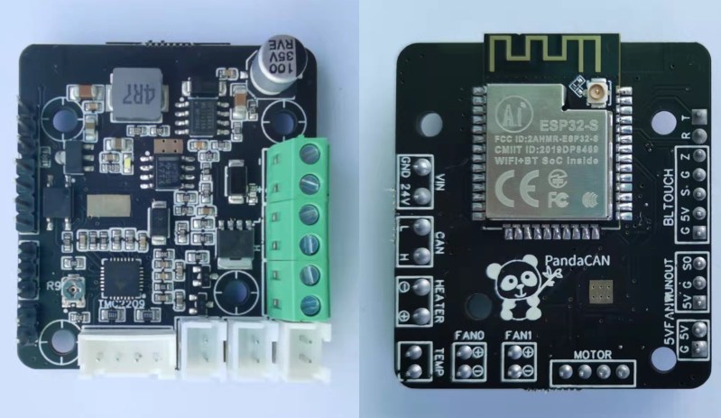
If you want to dig into the detail, the project GitHub has the schematics and code ready to go.


Duet3D’s Duet 3 ecosystem has had CAN bus for a while now, with multiple options for adding more axis motors, tool heads, and distribution of the CAN bus and power wires to multiple expansion boards.
I came to check if someone had already posted this, since it’s amusing when something is “new” and yet already in commercial production at the same time…
There’s a bit of a difference: The commercial product is closed-source. This is an open project that anyone can implement without having to pay Duet3D first. It’s sort of like how printing on a conveyor belt has been around in commercial products for decades, but we’re only seeing it widespread now because patents expired. You may have noticed this is Hack-a-Day, not Buy-a-Day. If buying commercial products is more interesting to you than building things, please go back to Amazon.
The Duet3D thing is closed, are you sure? Duet itself is open, why would they close this?
It’s not closed-source even after the above rant about it being closed-source.
From the license file: “This source describes Open Hardware and is licensed under the “CERN-OHL-S v2” or any later version plus the “Additinal Duet3D Licence Terms” outlined below, including any future updates.”
https://github.com/Duet3D/Duet3-Mainboard-6HC
@steve.
Thats completly wrong! All duet Software and Hardware is opensource. Even with kicad Files.
Devil’s advocate here, carefully reading Josh’s comment it’s not that he’s suggesting a commercial solution is any more interesting or worth a HAD post, just that it’s disingenuous to call something “new” when it is not in fact new. Counter devil’s advocate, this is still a new concept to be applied to an open source design and thus worth the merit of considering whether or not a commercial/closed source implementation exists.
There is Duet and Huvud and TurboCAN all open implementations of the same concept. So this is not new in any shape or form. The Huvud board can work over USB instead of CAN, for people like me who dislike the old automotive dinosaur.
As for being HAD post worthy – not the authority on that. I don’t mind reading about it.
Duet3D’s boards and firmware are opensource.
https://duet3d.dozuki.com/Wiki/Contributing_to_firmware_development
And as far as being commercial products, so is this PandaCAN.
Patents still in play with conveyor belt printers. That’s why all the ones you see in production are at 45* angles to the bed. That defeats the existing patents.
With the ESP32, one could reduce the wires down to just power and communicate wirelessly…
You may have problems with latency, especially if a endstop switch is mounted on the tool head. But that’s an idea worthy investigating anyway.
Given that (most normal) 3D printers have a strictly defined build area I would be curious if going with good, old-fashioned, IR would be viable:
You might need more than one transmitter arranged around the perimeter of the bed, so that you are free to put a receiver wherever on the head assembly you prefer without risk of the receiver being pointed away from the transmitter or blocked by part of the system; but that would all be static wiring out of the way of moving parts so it would be at much lower risk of strain/repeated flex/etc. damage.
Data rates wouldn’t be super crazy high; but LED to photodiode is very, very, simple compared to running some protocol over wifi and then decoding those into peripheral control signals; so getting lower latency seems viable; and somewhere between 1-10mb/s is hardly bandwidth starvation for a use case that’s mostly about sending providing time-critical control signals to a handful of motors and heaters; and receiving some somewhat less time-critical temperature and location feedback.
The heater, fan control can be implemented locally and not need a whole lot of real interaction other than temperature set points. The motor is just about the only thing that is time critical, but even then at the high level, you really worry about the feed rate, stop, retract.
There are IRDA transceivers that implements all the logic level signals to drivers/receiver and IR components. Most 32-bit microcontrollers have IRDA mode for their serial port. If not, there are IRDA encoder/decoder chips from Microchip, TI etc.
As for wires, it was a solved problem back in the days of dot matrix printers…
With microcontrollers on both ends you can just roll an OOKd UART over the power (and I’m waiting for someone to say “just return the current through the frame” or something horrible).
The whole problem, though, is that reducing “number of wires” is a bit pointless. Just get a flexible jacket of the right size and there’s no difference between six or seven wires and one.
When you start looking at things like interchangeable heads, multiple extruders, etc, the wires add up quick.
The head on my prototype mixing hotend has 30 wires… I looked at I2C, but that died simply because I didn’t have an ADC in my b
Still, what you say is true. All of those wires travel in one loom and have been happily bouncing around my printer for 3 years now with no issues.
Also on printers like Voron, the head moves so fast that the cable insulation dissolves after a few months in the cable chains. Reducing the number of wires is a real benefit.
That’s because you’re using the wrong cables. A Voron or similar should be using Continuous motion or Robotics cable for the moving components. I can get 18/12 long life continuous motion cable from Mcmaster for 18.60 a foot, and that will stand up to just about anything a Voron could possibly do, and have essentially all the wires you’d want, in a single cable. Rated at 20 million cycles with a 3 inch bend radius.
@Xenocrates said: “I can get 18/12 long life continuous motion cable from Mcmaster for 18.60 a foot…” Oof that’s outrageously expensive, even for continuous-flex 18/12 cable. For example, 1-99 feet of McMaster-Carr P/N 8082K22 PVC unshielded stranded 18-AWG 12-conductor continuous-flex cable costs $2.58 per foot. (Even that feels expensive to me; Supply-Chain + Inflation nonsense at work again?) Or maybe I’m missing something? See here:
https://www.mcmaster.com/8082K22/
More 18/12 continuous-flex cable options:
https://www.mcmaster.com/cable/cable-awg~18-12/use-for~continuous-motion/
Yup. I have silicone cables in mine (yet to replace them with HDPE or whatever the current recommendation is). Had a real head scratcher of a failure just last week where my extruder would go to half the poles in the stepper at very specific points on the bed. Took me aaaages to work it out. Ended up being a broken conductor in an intact section of silicone insulation. Crazy making. If you’re running silicone cabling 100% recommend getting very liberal with the silicone lubricant spray (pull your magnetic build surface out first). Proper multicore cable would be much smarter. Proper multicore with just 4 conductors would be even better. Super cool idea.
I’m currently in the stage of developing a wireless duet hub with MQTT for all my low latency devices. Duet sends (changes of) the object model wirelessly to the external box running an SBC with MQTT forwarding this to an esp32 connected to an 8 channel relay board triggering all mains devices. Its complicated but when finished worth the trouble. i was already getting insane with all those cables. When finished it will trigger the Coldend fan, nozzle Cam LEDs, 2x chamber heater, Solenoid for berd-air, berd-air itself, a cross-flow fan and a bathroom fan wirelessly. I’m on a mission here, at it WILL be completed this time , all in one box :)
i meant non – low latency devices here of course
Not sure if this is some elaborate sarcasm, because I wouldn’t trust wireless worth shit for low-latency precision operations.
right, the Relays sometimes need 1sec to trigger after switching it on my Dashboard. It needs some time. Hearters aren’t time critical though.
FYI: https://www.reddit.com/r/esp32/comments/qkwfph/ble_latency_and_optimization/
OP managed to get ESP32 BLE latency from 2ms – 12.5ms.
thx, not bad. I’ll go check out which connection is more stable, wifi or ble. i can’t tell atm.
There are already a number of CAN boards for 3d printers in the wild, like HUVUD and TurboCAN. Problem is that the chip shortage is hitting these pretty hard, so availability is a problem.
also no one is interested in CAN bus systems in 3d printing since it’s just another thing to configure (people like plugging things in more then configuring a firmware file)
I beg to differ, because it is quite the opposite: there’s a growing necessity to reduce the number of wires going into the printer toolhead, especially on the DIY ones – a Voron Afterburner toolhead can have up to 14 wires plugged on its devices, for instance. And the increasing number of options allowing that is proof that the demand is there, it’s just that the chip shortage hit it very hard, since microcontrollers able to do CAN are highly sought by the automobile industry, and people building 3d printers on their garages simply can’t compete with them financially.
Chips that can do CANBus that are rated for automotive use (static resistance, temperature range, etc) and with manufacturers promising production runs of a decade or more are sought after by car manufacturers.
This was a planned feature of Smothieboard v2 (spec from many years ago: goo.gl/dOjHhX ) but was taken out to simplify the first revision.
Right now, we plan to explore being compatible with the Duet CAN system instead (if it’s well designed enough), then once we are, move on to designing our own tools on top of that.
That’s for after the v2 boards go into production though.
Honestly I’d much rather a USB3 system than CANBUS. Now with USB-PD being able to deliver what…120w in some instances? It would be perfect for the kind of use that we currently have, comes with hot-plug capability, and also allows the ability to put hubs at the end of endpoints for inspection cameras, etc.
I think the idea behind the CAN bus on the Duet is too narrow-minded and we can do better. Klipper already allows multiple microcontrollers to coordinate among one another, it just needs the ability to enumerate endpoints and toolheads.
The Duet is such a pain in the ass to setup – none of the newly created M-codes make any god damn sense half of the time, and extensibility isn’t as easy because they’ve decided that configuration should be completely separate from everything else.
I’ve been working on a system such as this in my spare time, I just don’t have the cycles or the programming experience to contribute it correctly to the ecosystem. I won’t ever use Duet boards, they’re incredibly overengineered for what they do, and too convoluted to set up. Hell, even the Duet team won’t give you a simple SD card image to flash, they say “go to X github, and download these folders, then go to Y github and download these folders, then put Z folder in the root directory and Y folders within Q, and voila your Duet 3 might boot up now.”
CAN has some useful features that aren’t so easy to do with USB3. Things like only two wires, automatic message prioritization, short/open circuit detection on the bus, high noise tolerance, messages are broadcast, multiple nodes on the same link and easy availability on a lot of microcontrollers. There’s disadvantages too, such as low data rates (250Kbit up to 5Mbit) and termination requirements. It also doesn’t have any of the confusing mess that is USB-PD :)
you sir just made my day :P …. emphasis on the “might boot up part” I’m a techie by nature and honestly like you said they really don’t make it easy for you. being new to the ecosystem it took me a solid week on and off to get the thing booting… even a straight micro with daughter-board and firmware like grbl makes more sense to me that the duet stuff. i really like the web connectivity and interface but seriously… it comes at to high a cost.
back to the topic at hand if you have to add electronic to each endpoint anyway you might as well go with something completely new like 2 wire combined data and power lines or a command queue system with timing pulses to sync all the component.
I’m sorry it’s too complicated for you.
My experience is much better:
First time: I go to the RRF configurator, type in my configuration (or upload my existing .json file if I only want to change a few things) create the configuration, download the .zip file and upload it to my printer via the web interface.
The system unpacks, installs and reboots.
To run an update, I download the .zip file from the forum/github, upload it using the web interface and everything installs and reboots.
It’s pretty slick for an old embedded-systems developer like me.
This system updates the mainboard, the LCD and all the toolboards automatically, so it’s a complete systems update.
Anyway, I’m sure you have something more simple that fits your needs and that’s awesome.
Canbus is low-level and low latency when compared to USB.
There’s a reason it’s heavily used in automotive and industrial applications for automation, robotics and reliable communication.
the idea certainly has some appeal, especially if you have a lot of devices on your end effector. mine is just fan+heater+thermistor, and the resulting hot end is so light that i’d actually be hesitant to add even a small PCB to it.
but i think the disadvantage of running a bundle of wires is a little overstated. i actually have an extra pair of conductors running simply because a ribbon cable was handy when i built it. and i don’t think most of the failures tend to happen over the length of the cable anyways…my wires are all zip-tied to the teflon filament tube (bowden), which does a good job of preventing tight-bend or pinch injuries to the cable. the real hazard, from what i imagine and what i’ve read about, comes from vibrational (or snag??) damage to the connectors or mountings (especially, the thermistor popping out). and this doesn’t seem to address that at all, because there are still local connectors and wires running from the PCB to the components.
one way this could become real compelling is if the whole hotend could be assembled directly on a PCB…it’s hard to imagine how to physically arrange the thing so that the heater, thermistor, and fan(s) would all be aligned for direct/permanent mechanical connection to a PCB…let alone an extruder and bed sensor. not sure it’d be brilliant to have a heater that close to it. but it would be pretty slick if they were! anyways, if that happened then it would be time to start working to reduce the number of wires in the umbilical. otherwise, i think it doesn’t really matter…the underlying downsides remain.
The idea has merit, but introduces a new challenge for hosting electronics in a heated chamber. Electronics don’t like the heat, so if printing with higher temp plastics the CAN bus on the hotend will die sooner.
Both CAN bus and microcontrollers are available int mil temp range (up to 125C).
And in case you need it, there are also radiation hardened CPUs. Don’t worry, we’ve got you covered.
How to spot a good hack: They did it because they CAN.
Back when CAN was first introduced to cars I thought it was a great idea – it would simplify the wiring of the car and “increase” reliability- those nasty wires break sometimes. But after a few decades of playing with CAN bus cars and I can appreciate some of the advantages it has brought but swapped a few simple wires for a bunch of complex overhead. Just to add Bluetooth to my car radio now requires more wires and a microcontroller and a CAN controller and a line driver and more connectors and a bunch of code and a bunch of other tools for development.
It’s increased the number of points of failure way over and above the cost of a few strips of copper.
I like it because it’s interesting but the improvements to the system aren’t proportional to the increase in complexity.
Just because we CAN doesn’t mean we should
That’s more manufacturers being dicks and using the highly integrated nature of canbus to essentially erect a walled garden.
Which is why DRM and copy protection for firmware and operating systems is the biggest pile of BS.
So instead of having one component go out due to a bad wire, we can have the whole hot end go down for the same fault? How is this an improvement?
Fewer wires means fewer failures.
Also, running analog signals for temperature sensing next to PWM high-current signals for extruder heaters doesn’t make for a good, reliable system design.
I do agree with this however, these boards actually add a lot more components as now everything needs a CAN bus transceiver, its own micro and the circuitry to support them. Great for modularity, but it is more parts which can fail. Because of this i think they are great for people who want to build their own printer which might be somewhat non standard… but not so great for people wanting to sell printers.
I would say the biggest benefit are that the CAN bus means you can now have fairly long wires between your nodes (big printers), CAN is pretty resistant to harsh environments, and that the system becomes easily expandable, want more sensors or want to swap out motor drivers/motors then you just need to swap/add a few modules. I would imagine it also means you can use almost anything (with a CAN transceiver) as the control unit which is pretty cool.
Fewer wires also means less redundancy / resiliency. To compound the problem, having a larger bundle of wires creates a stiffer frame for those wires. Having fewer wires may inadvertently result in MORE wire failures as they flex more and more often leading to hardening and breaking.
Again, besides the obvious (over)engineering boner that people get from CAN bus, I don’t see any advantage in this situation.
Fewer wires between points A and B, more cr*p. This adds a TON of complexity, littering microcontrollers and other electronics all over the printer and adding many more points of failure.
Yep. If you have a power surge for whatever reason (lightning used to kill my modems), this would make everything much more difficult to troubleshoot and repair.
Fatal Error: 2nd paragraph, 5th line, 6th word: if statement missing
About 9 years ago, I was considering building a CAN-based printer as a warmup before a Sercos III-based printer/mill/lathe/all-in-one machine. Sercos III runs on common Ethernet cables and can be used in a bidirectional ring topology that can withstand without interruption (and presumably report) any one cable breakage. It also carries 100 Mbps Ethernet, so each module could have its own web interface or file share for configuration. On the other hand, it needs more conductors than CAN, and it’s less popular. On the gripping hand, though, you can just use a commodity Ethernet patch cable to the head, and if it breaks you can wait until the print is done and then replace it in a few seconds, rather than having to repair it or build a new custom cable while the print is paused (or, more likely, start the print over after the repair). That could be especially helpful if you frequently do long or otherwise high-value prints, or if you’re doing mass production.
(There’s also Sercos II, which I haven’t looked into, but it’s said to be conceptually similar, and it uses fiber-optic communication, which might be better for fast-moving 3D printer heads…? And what about LIN, which, like CAN, is commonly available in microcontrollers?)
Don’t over optimize life!
I am surprised nobody has mentioned Snapmakers, system; using CAN BUS from the very start a few years ago; offering plug and play 3D filament printing ; CNC; laser engraving
If you know how to do proper strain relief this is an unneed extra cost.
Yes, I may have many wires going to the hotend but I have also seen the strange failures with CAN bus based motorcycle systems when someone has a connector not tightly connected — all sort of wrong reports/self diagnostics.
CAN bus was meant to deal with HIGH noise enviroments — don’t think my printer qualifies for that.
Now on the flip side, most printers are wired badly.
The fan gets power and ground — 2 wires
The hot end gets power and ground — 2 wires
the layer fan get power and ground — 2 wires
Since with the mosfet output we are switching the ground connection, we could eliminate eliminate 2 power wires to start. and more depending on what other fans, sensor or dooddads you add.
These are hobbyist machines — K.I.S.S. needs to be applied — that excludes CANbus in my mind.
I was hoping to one day try something similar with Modbus & RS-485.
Is that still worth trying? I thought CAN bus required expensive chips, specialized hardware, etc… Does CANbus have an advantage over Modbus? Besides bandwidth? There isn’t that much bandwidth needed in a 3d printer anyway right?
Hi, i am interested in implementing can into my 3d printers and even starting to design some pcb’s. The printer i am using at home i am sure the mellow fly sht bord and usb can receiver wil work fine.
My interest is more into high speed printing using servo’s. When printing 500mm up to 1500mm i see that the duet 3 bord is limmited with the Step Pulse Timing roughly 80khz, the printer i am looking a can implementation for needs arround 200khz Step Pulse Timing per servo..
Does anyone know why de duet expesion bord is limmited to 80khz and what the kb/s is?
https://duet3d.dozuki.com/Wiki/Duet_3_Expansion_1XD
Does anyone know the Step Pulse Timing limmitations of the now available Mellow Fly-sht42/36 and Bigtreetech EBB36 EBB42 ? i know the EBB36 and EBB42 have a max 250kb/s and fly-sht42/36 500kb/s? I have the feeling the limmiting factor is the used MCU.